SPIRIT Phantom Holder Assembly Instructions
Document Version: 1.0
This document describes how to assemble the sample holders for the SPIRIT Phantom. The sample holders are specific to head coils, currently two are supported: Siemens 32 channel coil, and Siemens 64 channel coil. Both are very similar in design and construction.
Siemens 32 channel Coil
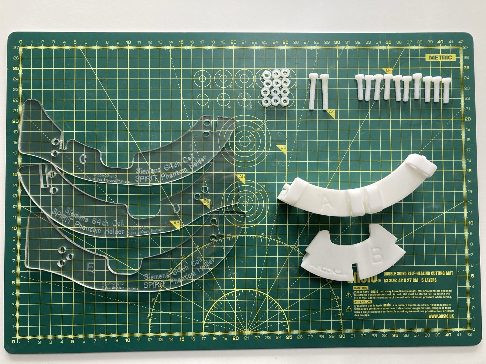
Parts
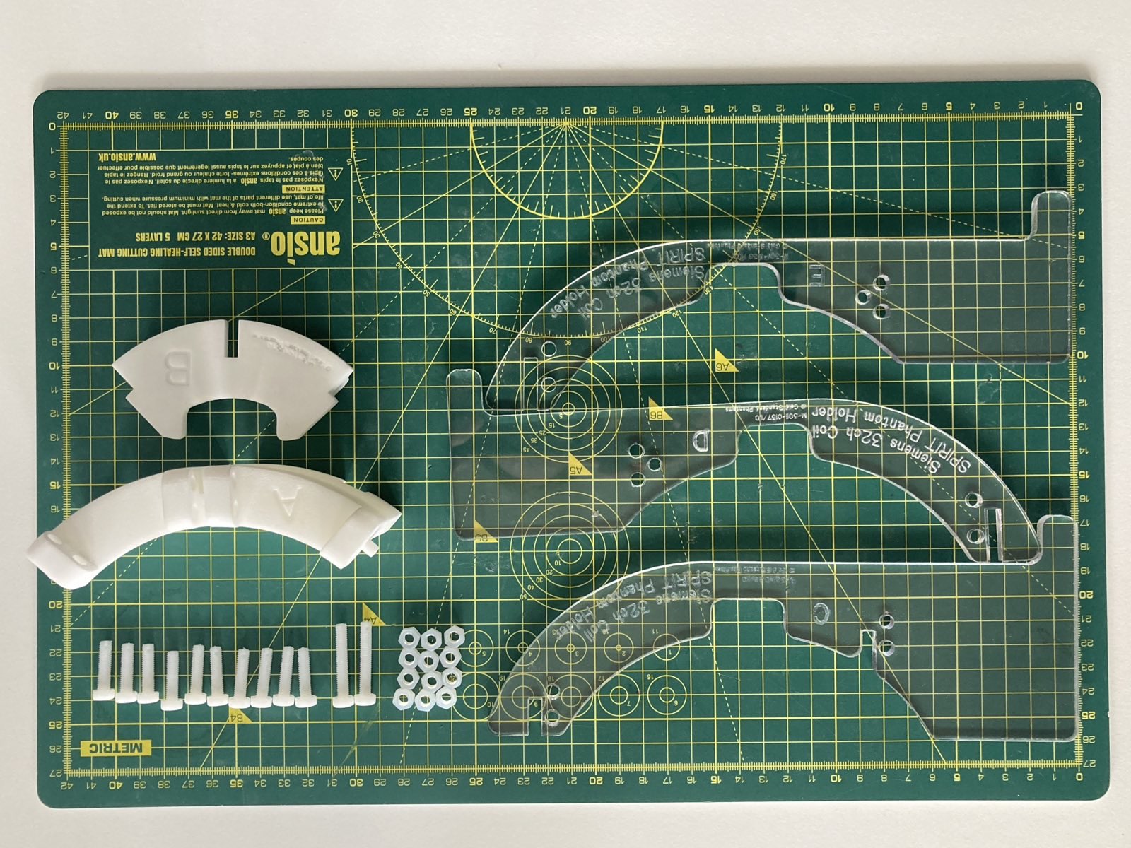
Ensure parts C, D and E have Siemens 32ch Coil on them.
Identifier | Description | Quantity |
|---|---|---|
A | Main brace | 1 |
B | Nose brace | 1 |
C | Siemens 32ch Coil Centre Support | 1 |
D | Siemens 32ch Coil Left Support | 1 |
E | Siemens 32ch Coil Right Support | 1 |
F | M5 x 20mm Nylon Hex Head Screw | 10 |
G | M5 x 30mm Nylon Hex Head Screw | 2 |
H | M5 Nylon Nut | 12 |
Assembly Instructions
Description | Image | |
|---|---|---|
| 1 | Fit Part A over the rear notch of Part C so that the fixing holes align | 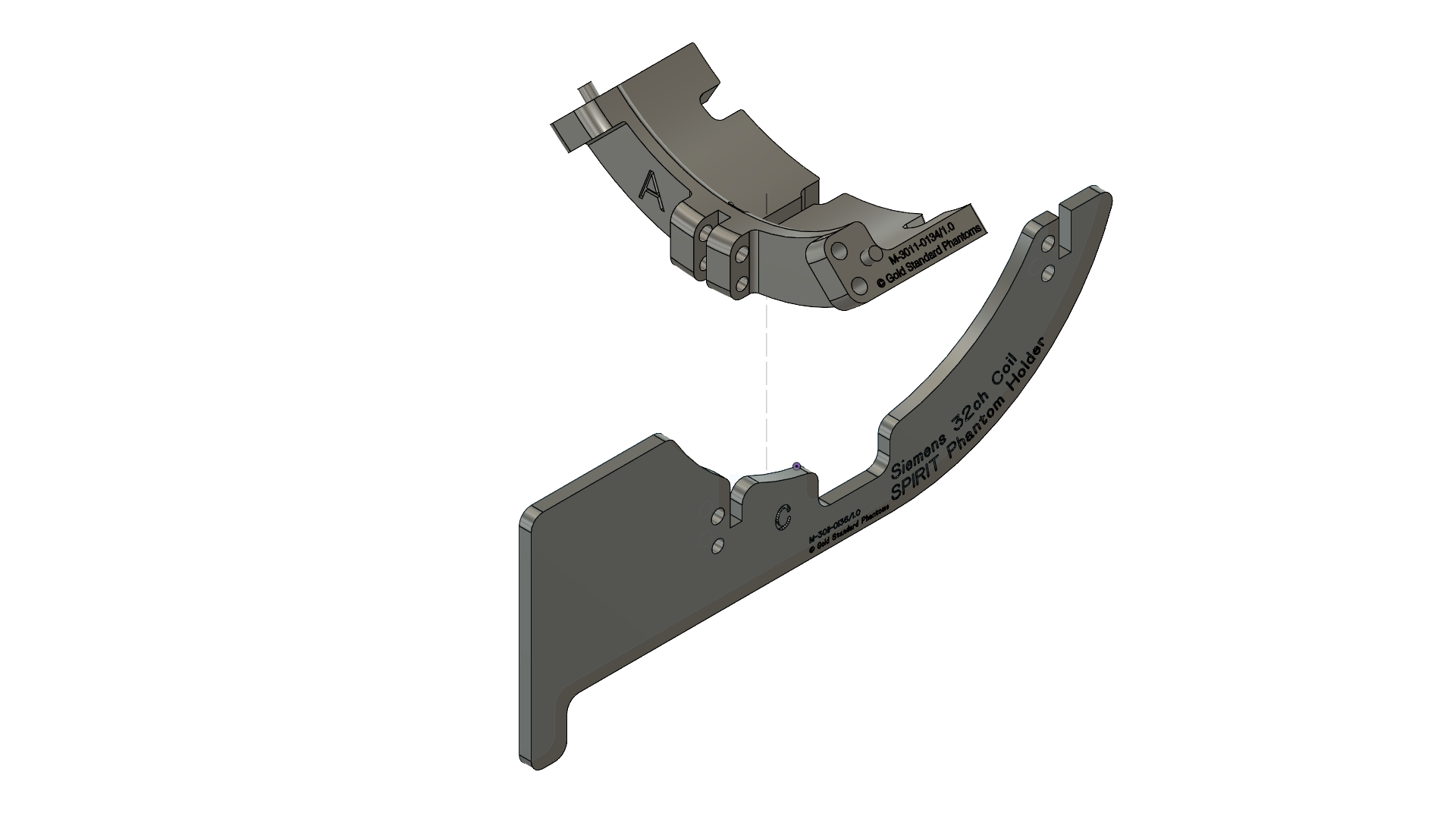 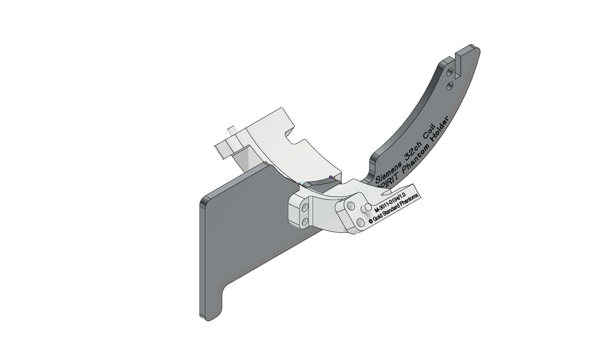 |
| 2 | Push two G screws through the holes then add two H nuts Tighten the so they are finger tight | 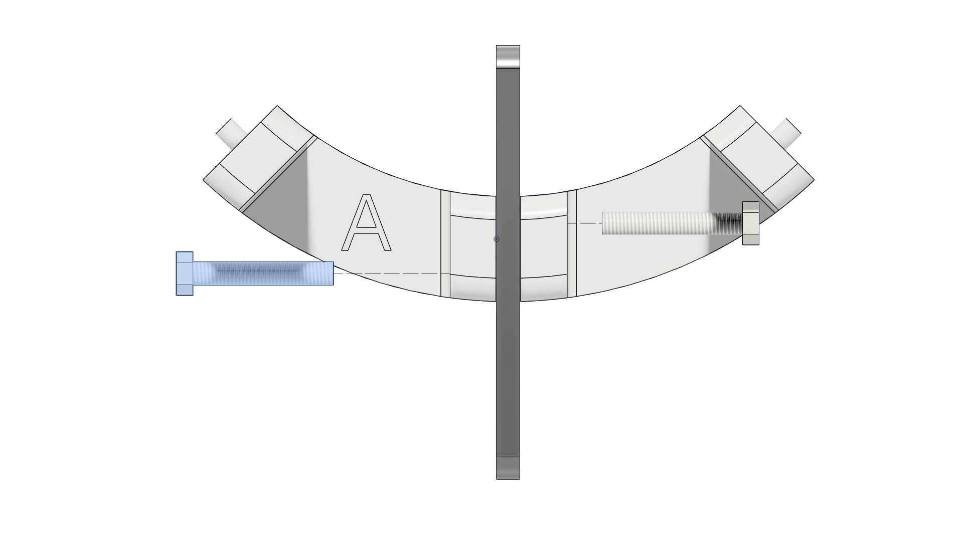 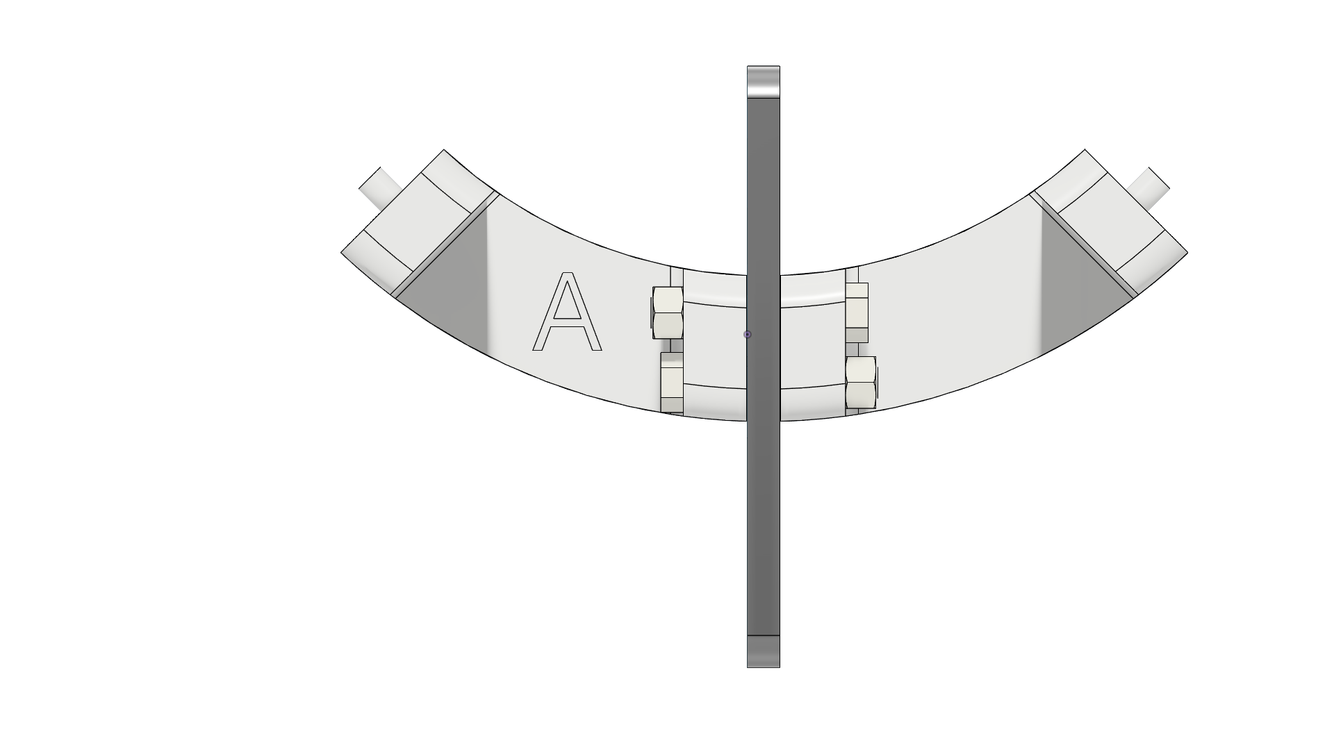 |
| 3 | Fit Part B it to the front notch of Part A | 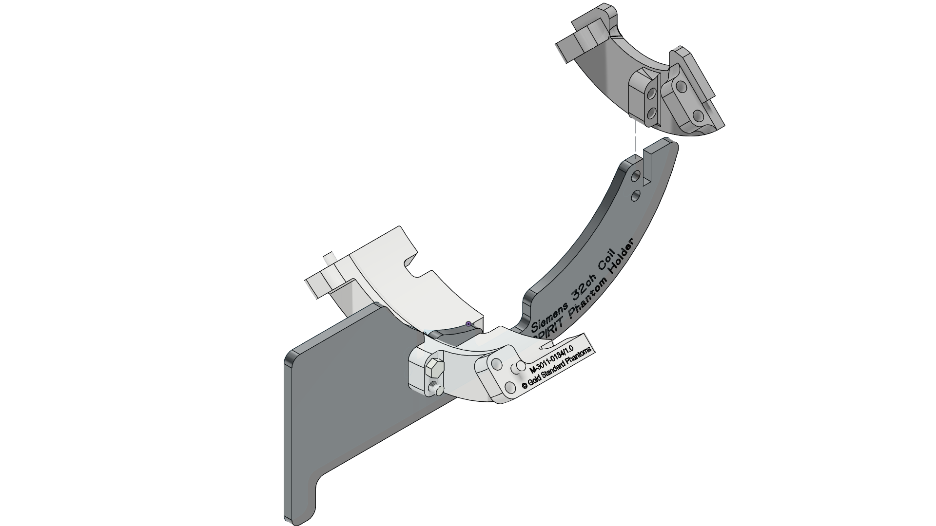 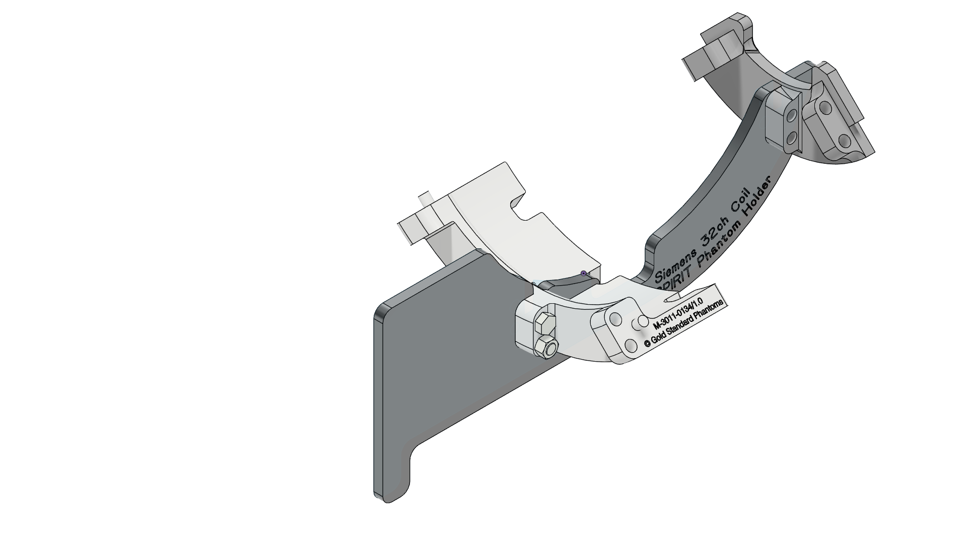 |
| 4 | Taking two F screws and two H nuts push them through the fixing holes by hand then add the nuts and tighten by hand (finger tight). | 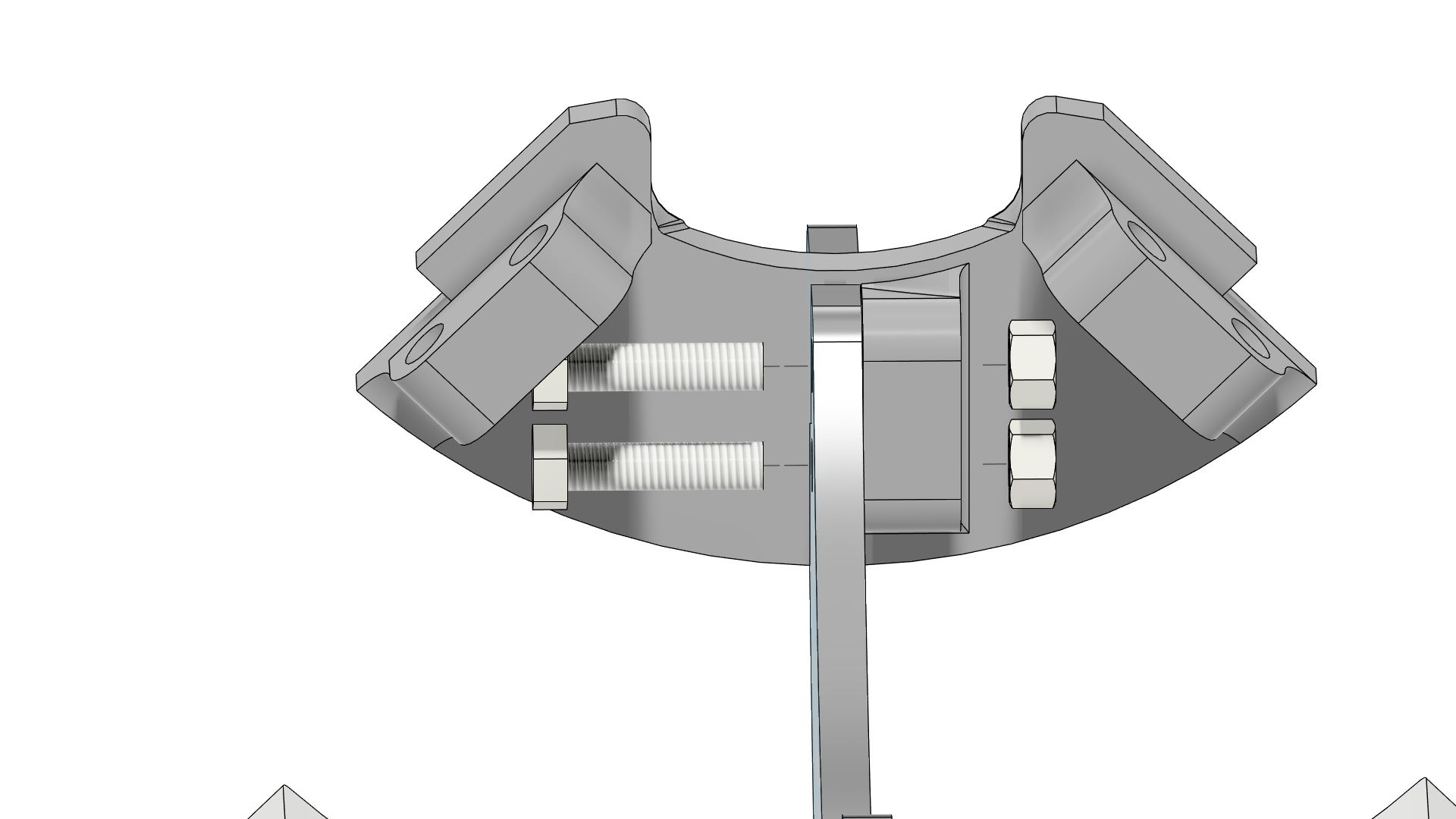 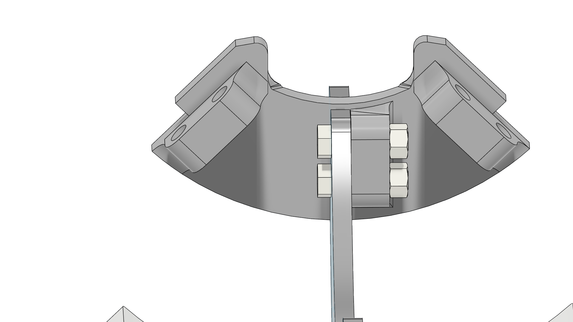 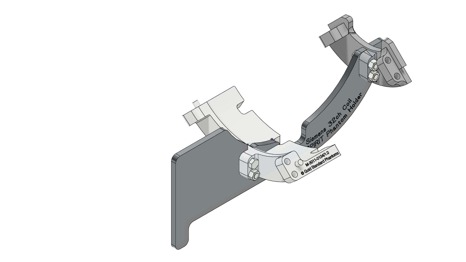 |
| 5 | Add the left support, Part D. The peg on Part B mates with the hole on Part D. | 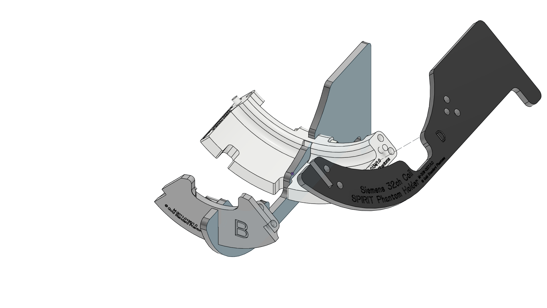 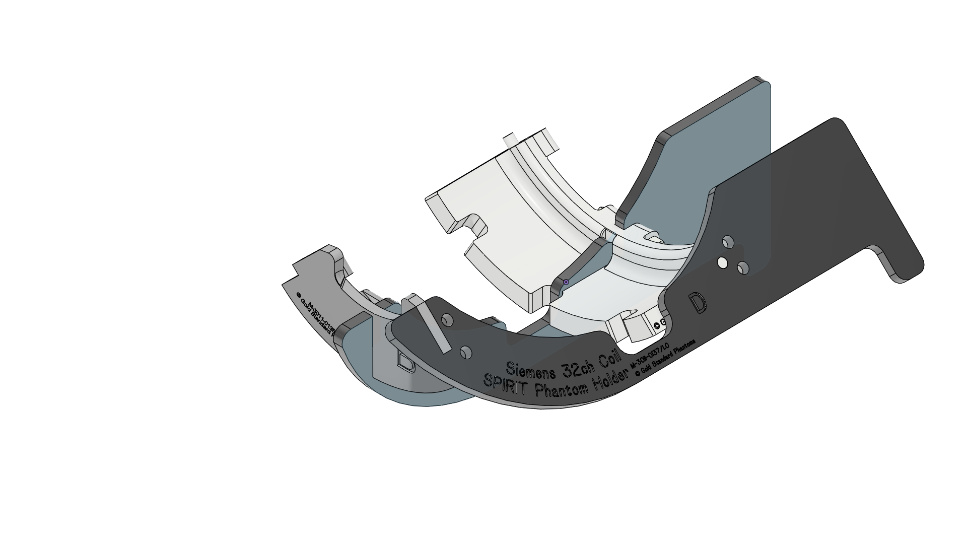 |
| 6 | Fit four F screws into the holes between Part D and parts A and B. Add four H nuts and tighten by hand (finger tight). | 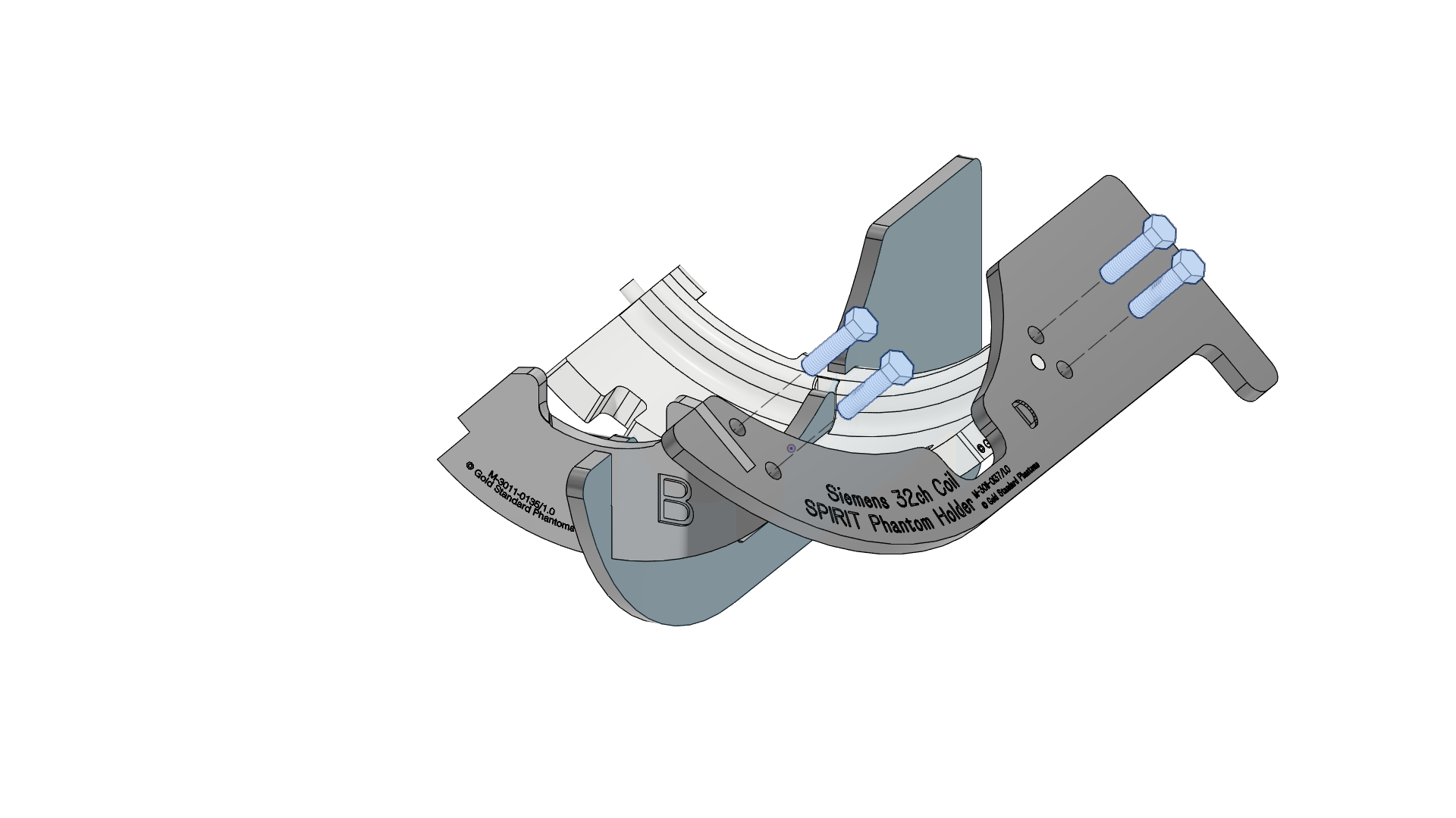 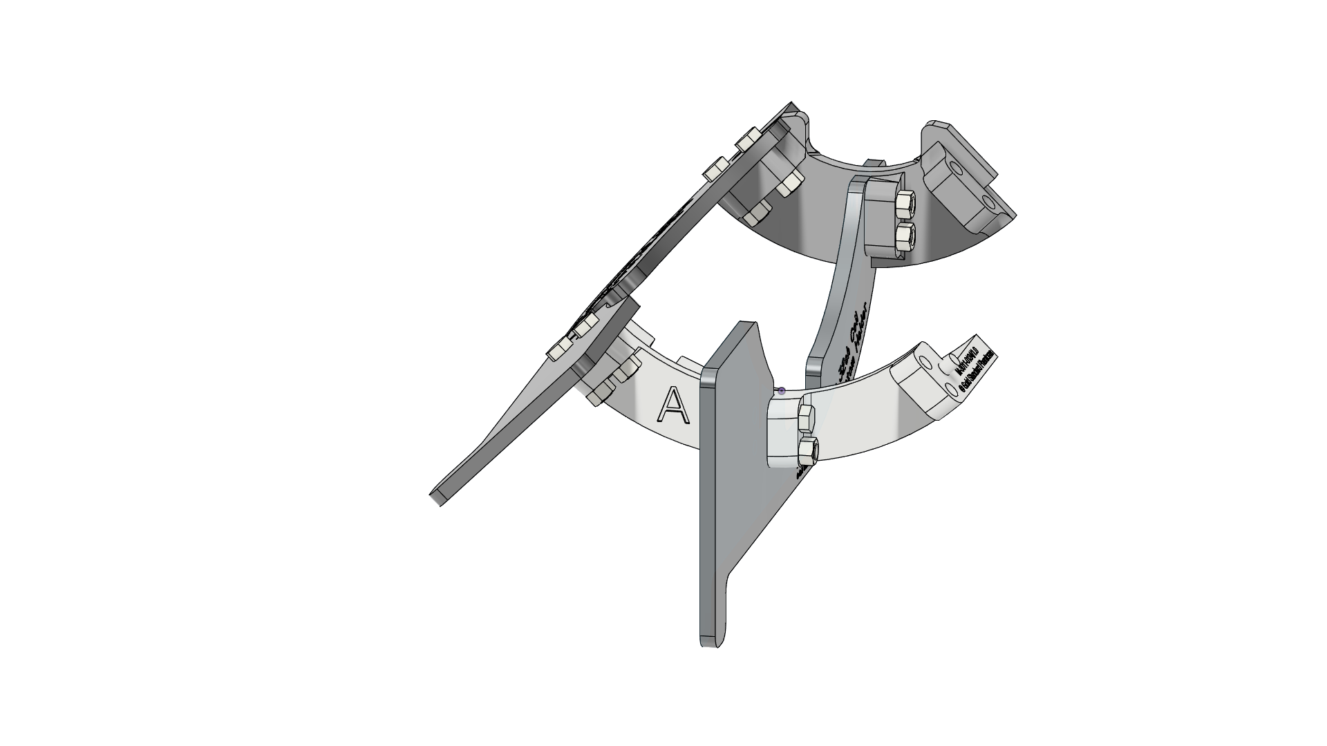 |
| 7 | Add the right support, Part E. The peg on Part B mates with the hole on Part E. | 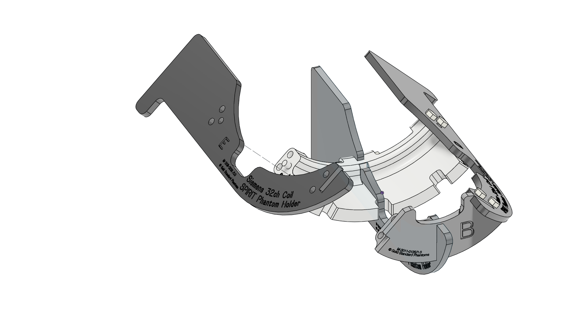 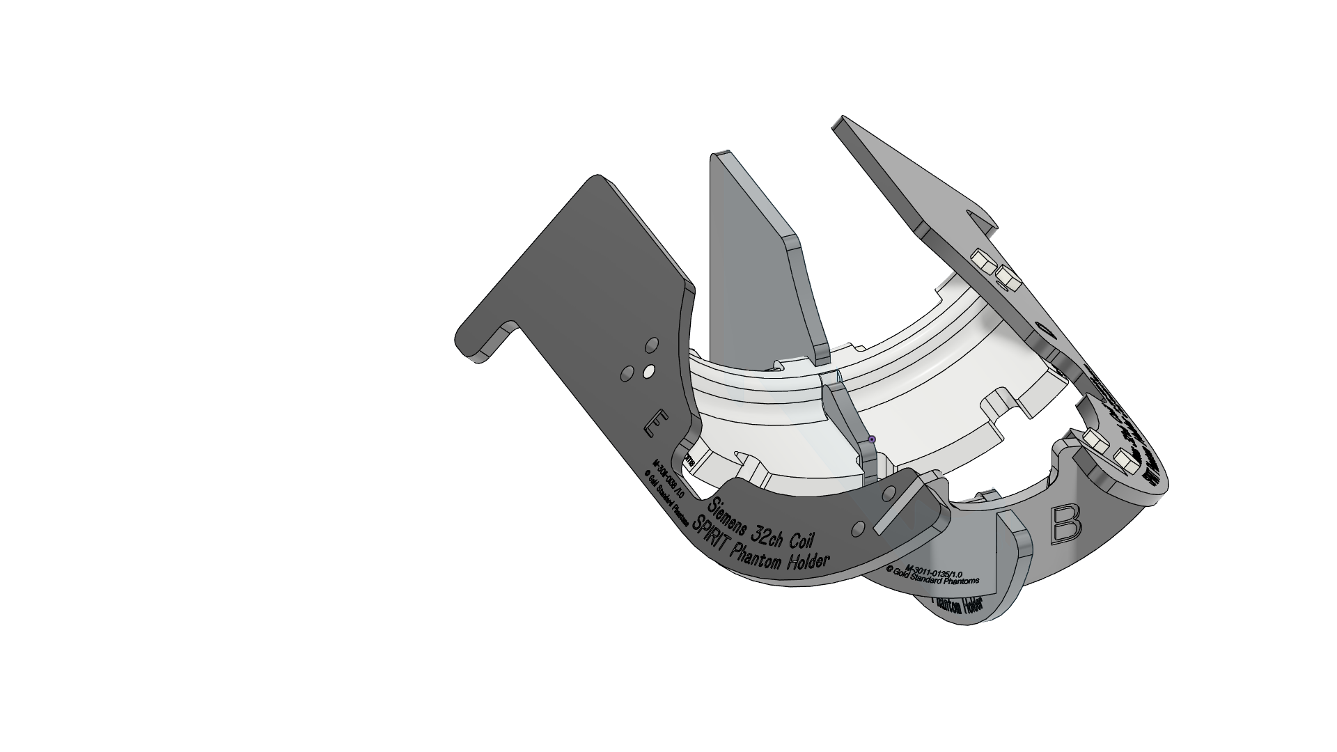 |
| 8 | Fit four F screws into the holes between Part E and parts A and B. Add four H nuts and tighten by hand (finger tight). | 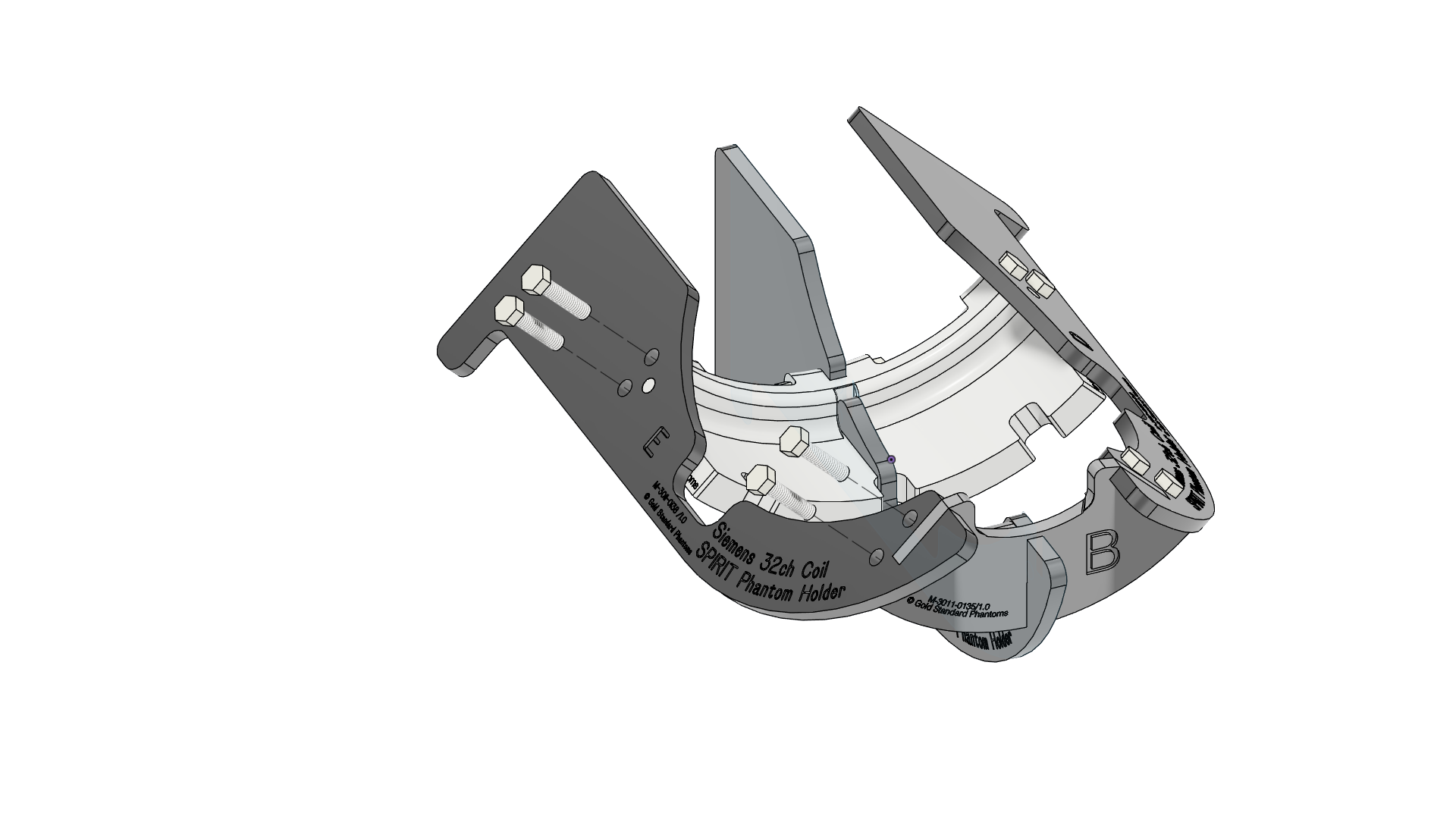 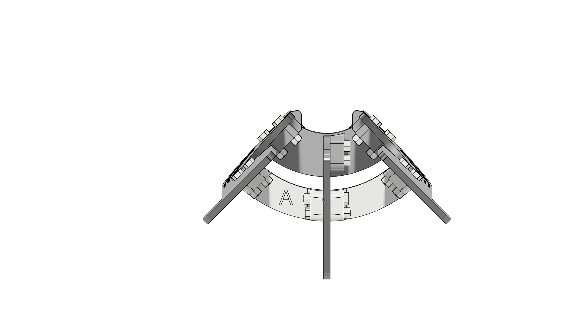 |
| 9 | Congratulations you have completed the assembly of the Phantom holder | 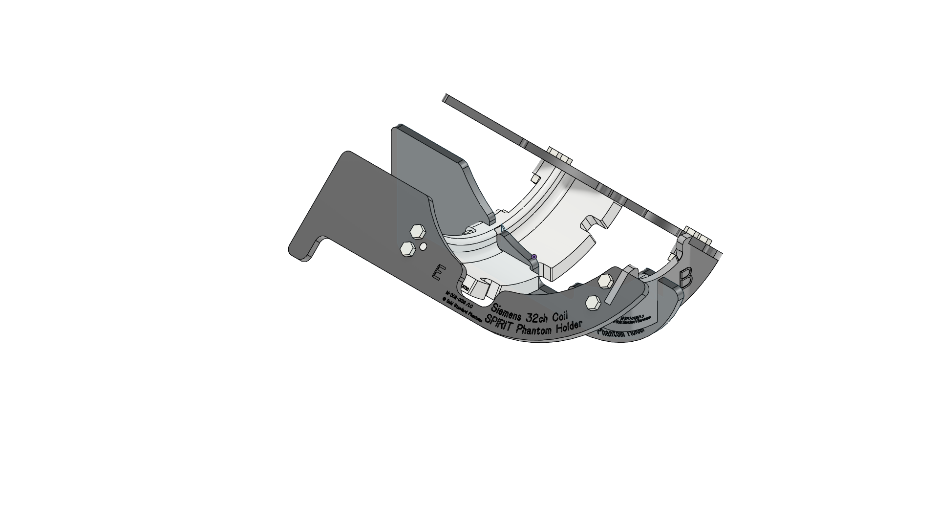 |
Using the Phantom Holder
| 1 | Placing the SPIRIT Phantom The Spirit Phantom holder has notches in Part A that the screws in the phantom fit snugly into, indexing its orientation. The Phantom should be installed in the Phantom Holder with the Label facing up
| 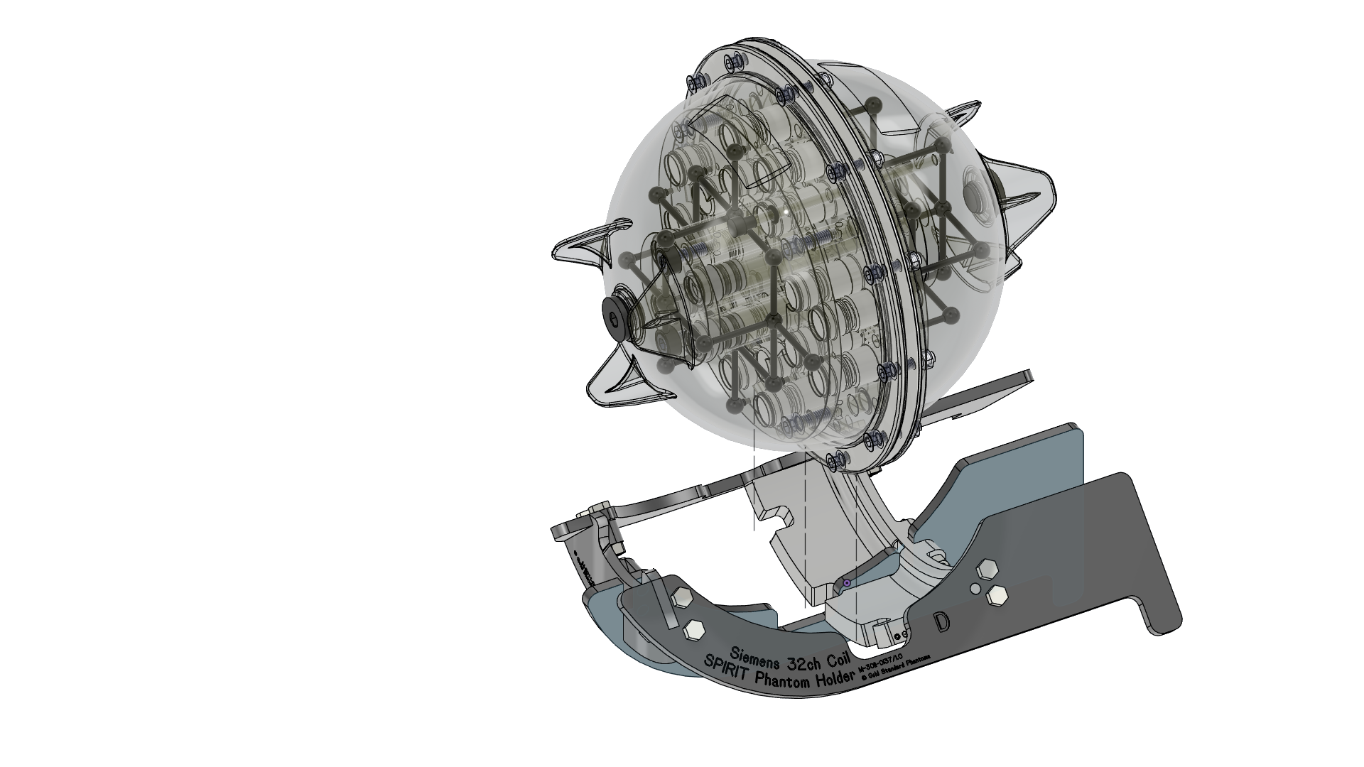 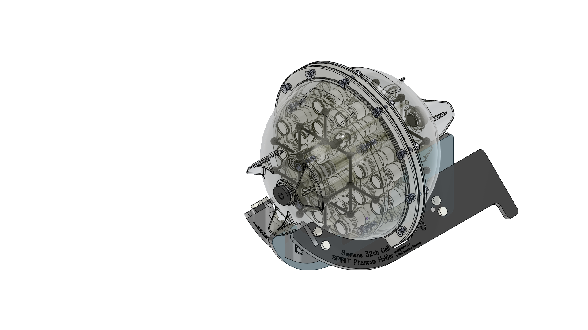 |
| 2 | Placing the holder in the Siemens 32ch Coil The Phantom and phantom holder can now be slid into the Seimens 32 ch head coil | 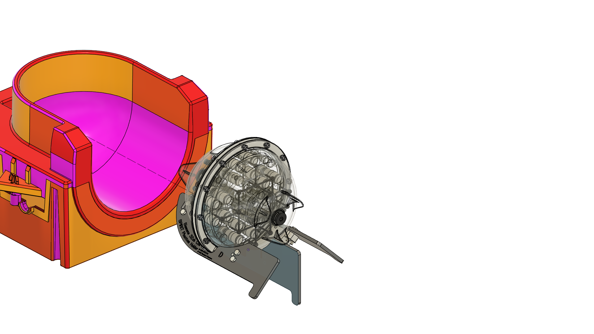 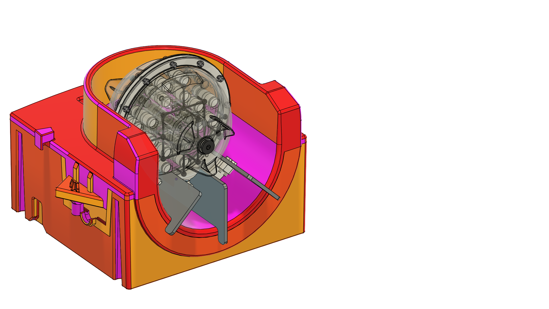 |
| 3 | To ensure the rotational position of the phantom take the rotational alignement jig and place it over the lip of the Coil using the Notch labelled A. The flat part of the jig will sit against the nut on the phantom at the 10 o’clock position. The jig then may be removed. | 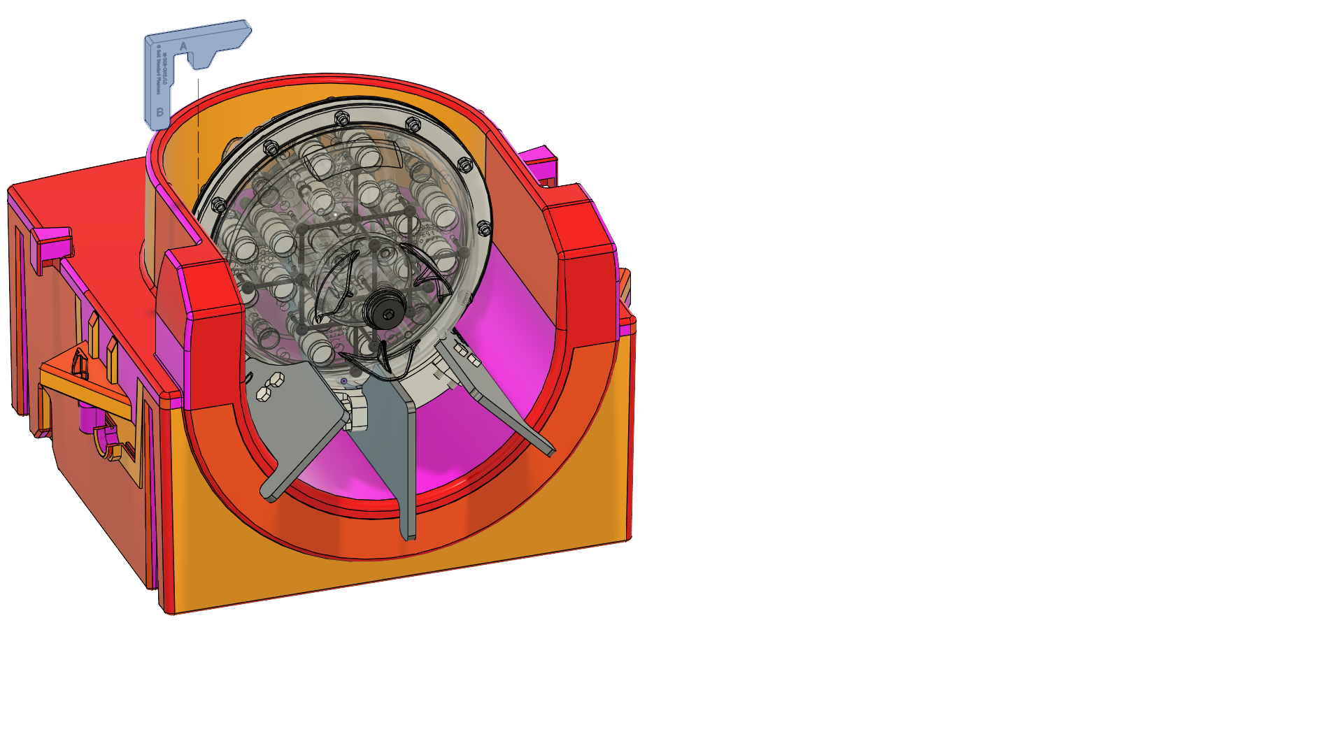 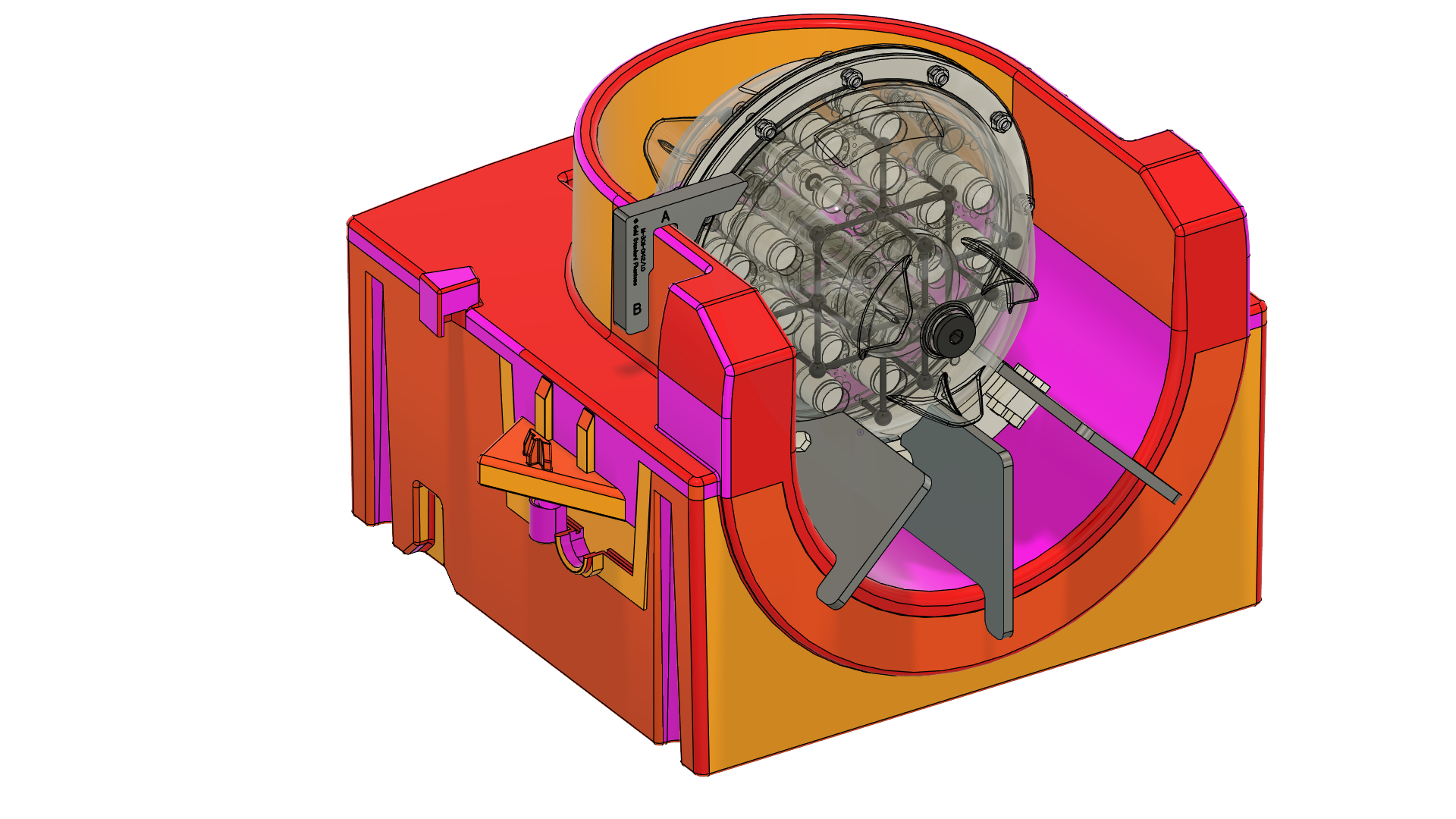 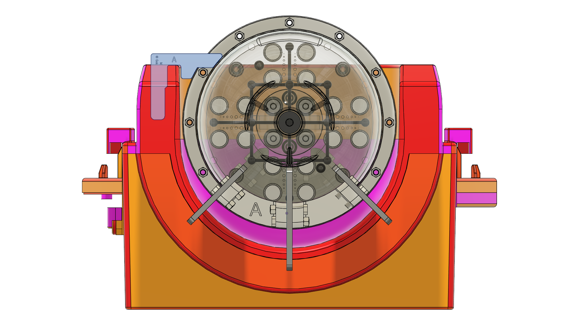 |
Siemens 64 channel coil
Parts
Identifier | Description | Quantity |
|---|---|---|
A | Main brace | 1 |
B | Nose brace | 1 |
C | Siemens 64ch Coil Centre Support | 1 |
D | Siemens 64ch Coil Left Support | 1 |
E | Siemens 64ch Coil Right Support | 1 |
F | M5 x 20mm Nylon Hex Head Screw | 10 |
G | M5 x 30mm Nylon Hex Head Screw | 2 |
H | M5 Nylon Nut | 12 |
Assembly Instructions
Description | Image | |
|---|---|---|
| 1 | Fit Part A over the rear notch of Part C so that the fixing holes align | 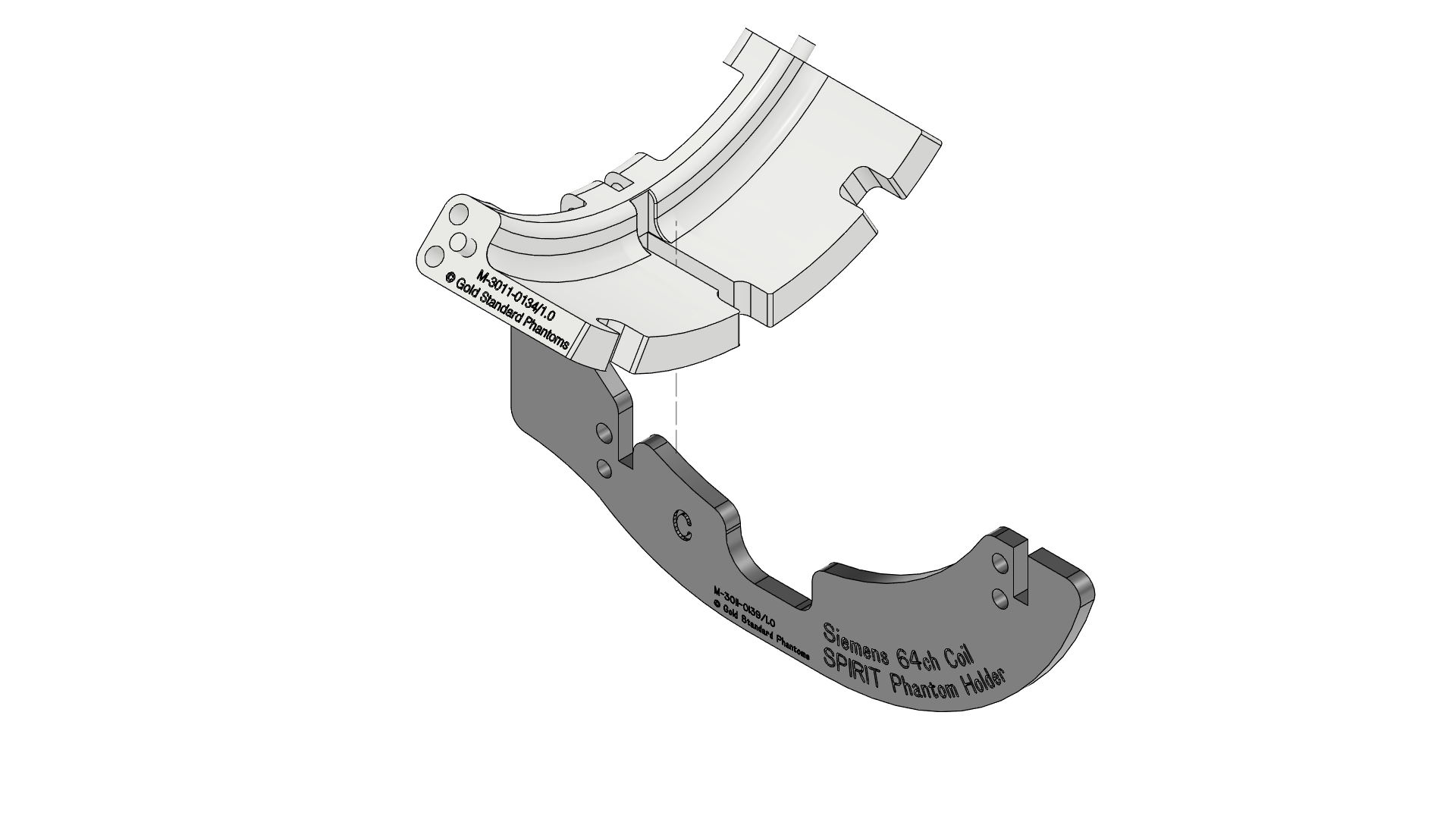 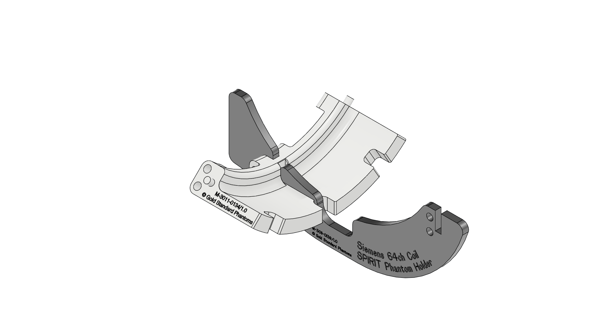 |
| 2 | Push two G screws through the holes then add two H nuts Tighten the so they are finger tight | 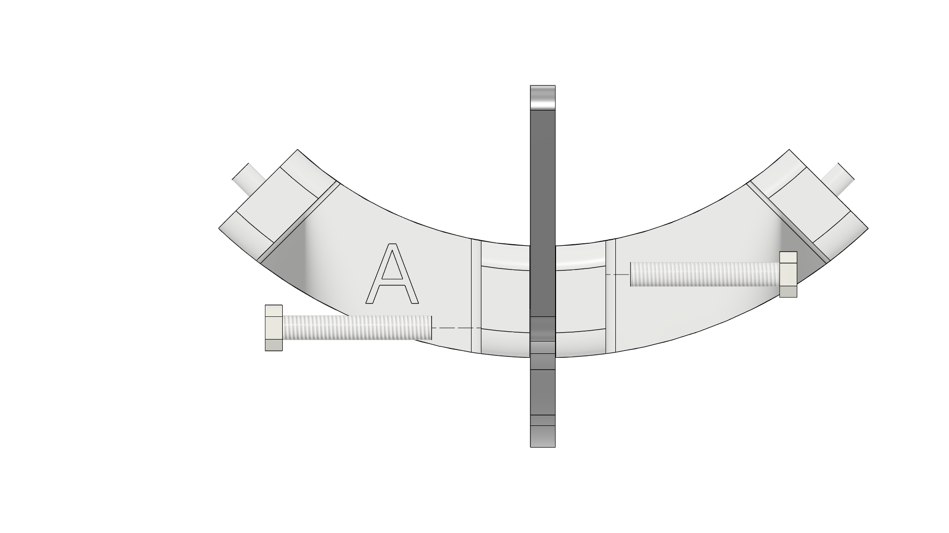 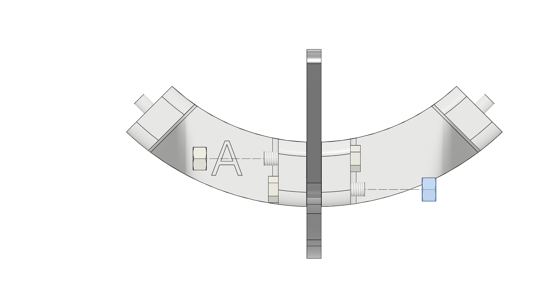 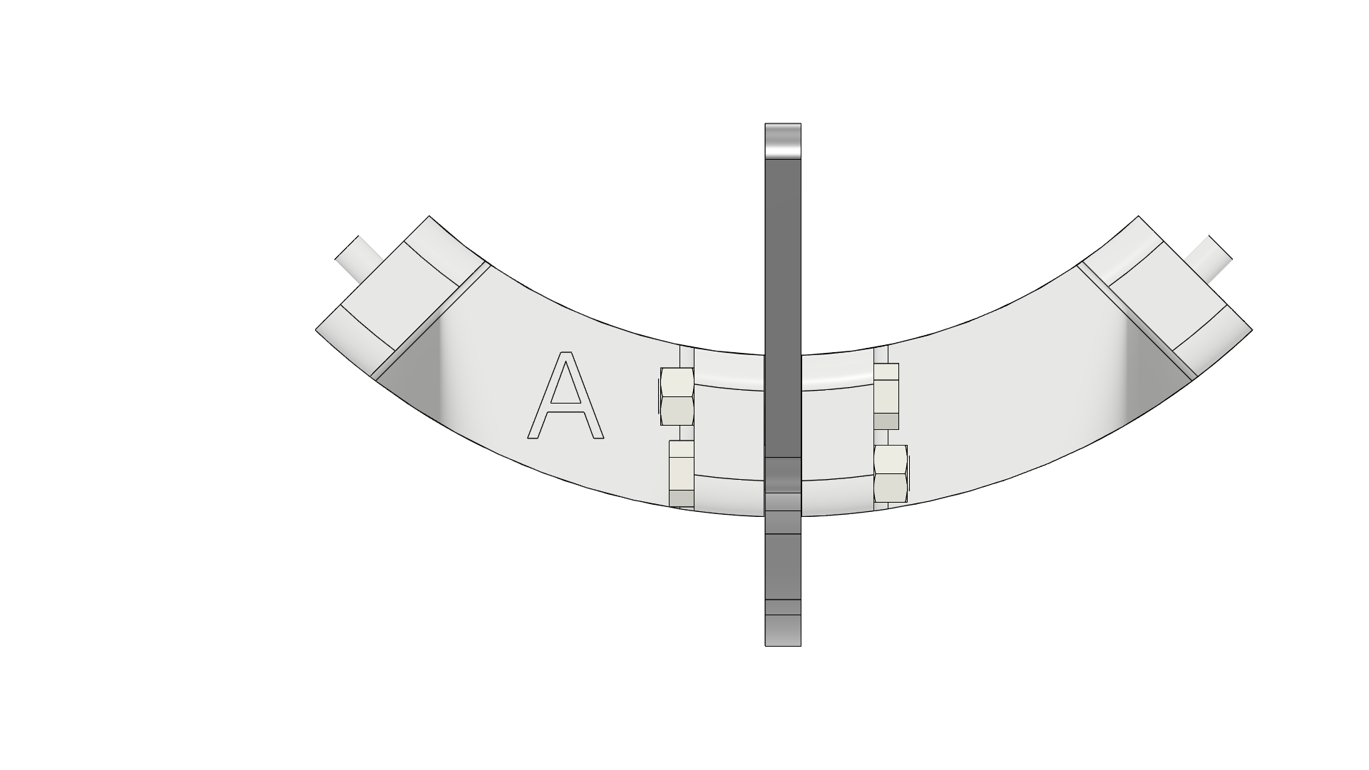 |
| 3 | Fit Part B it to the front notch of Part A | 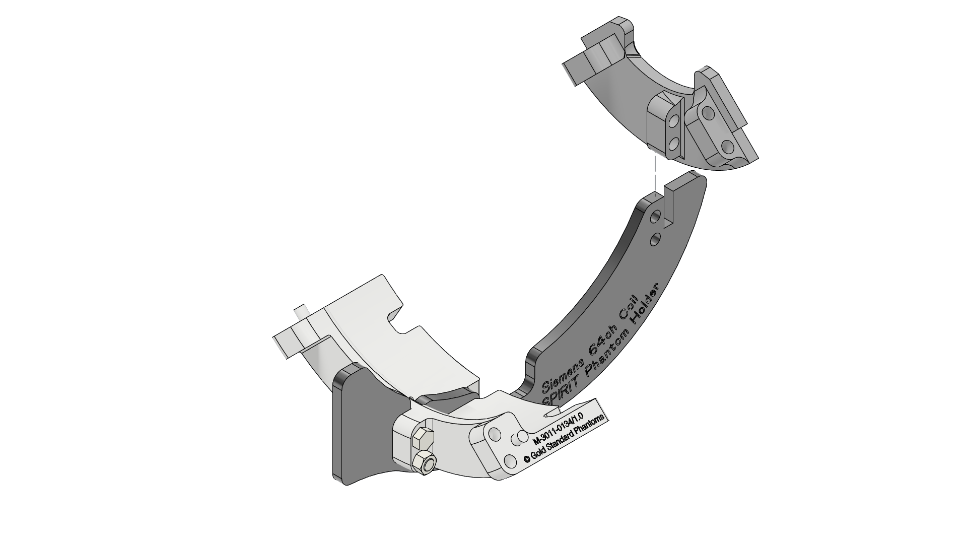 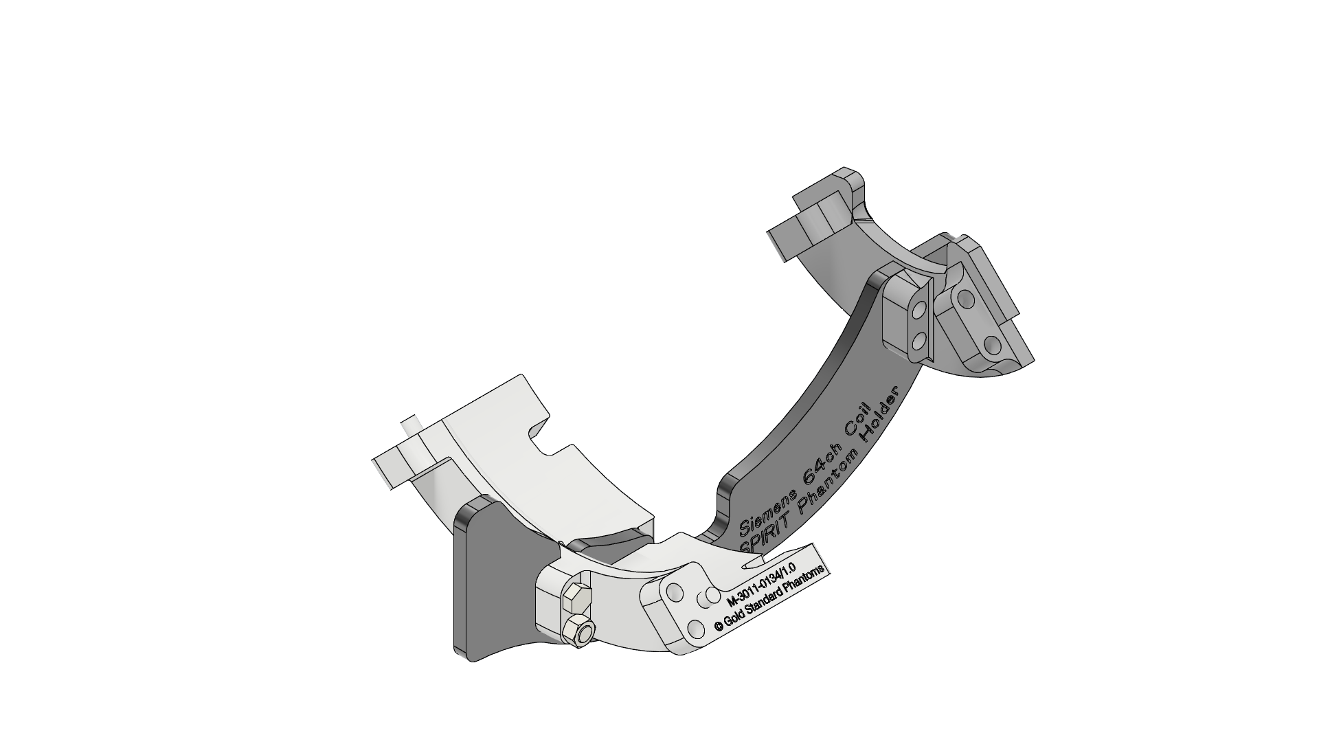 |
| 4 | Taking two F screws and two H nuts push them through the fixing holes by hand then add the nuts and tighten by hand (finger tight). | 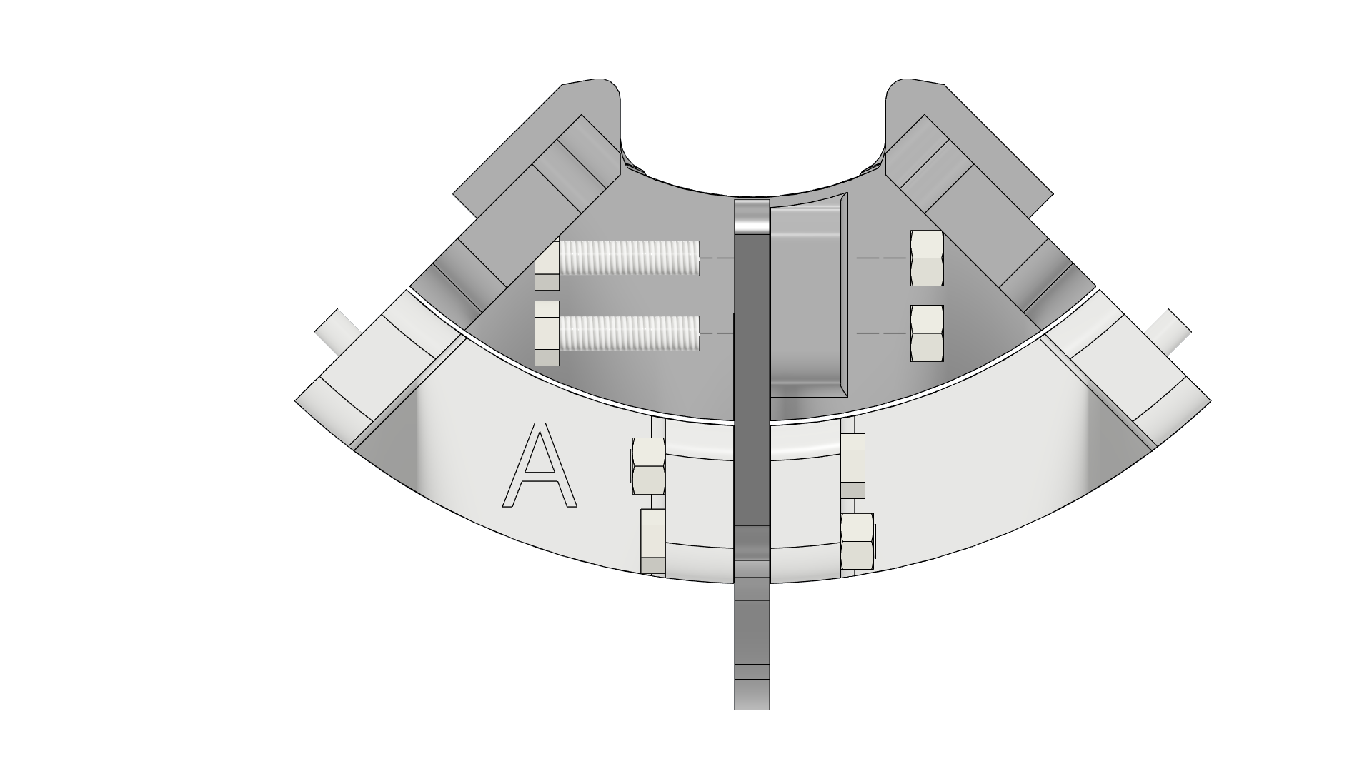 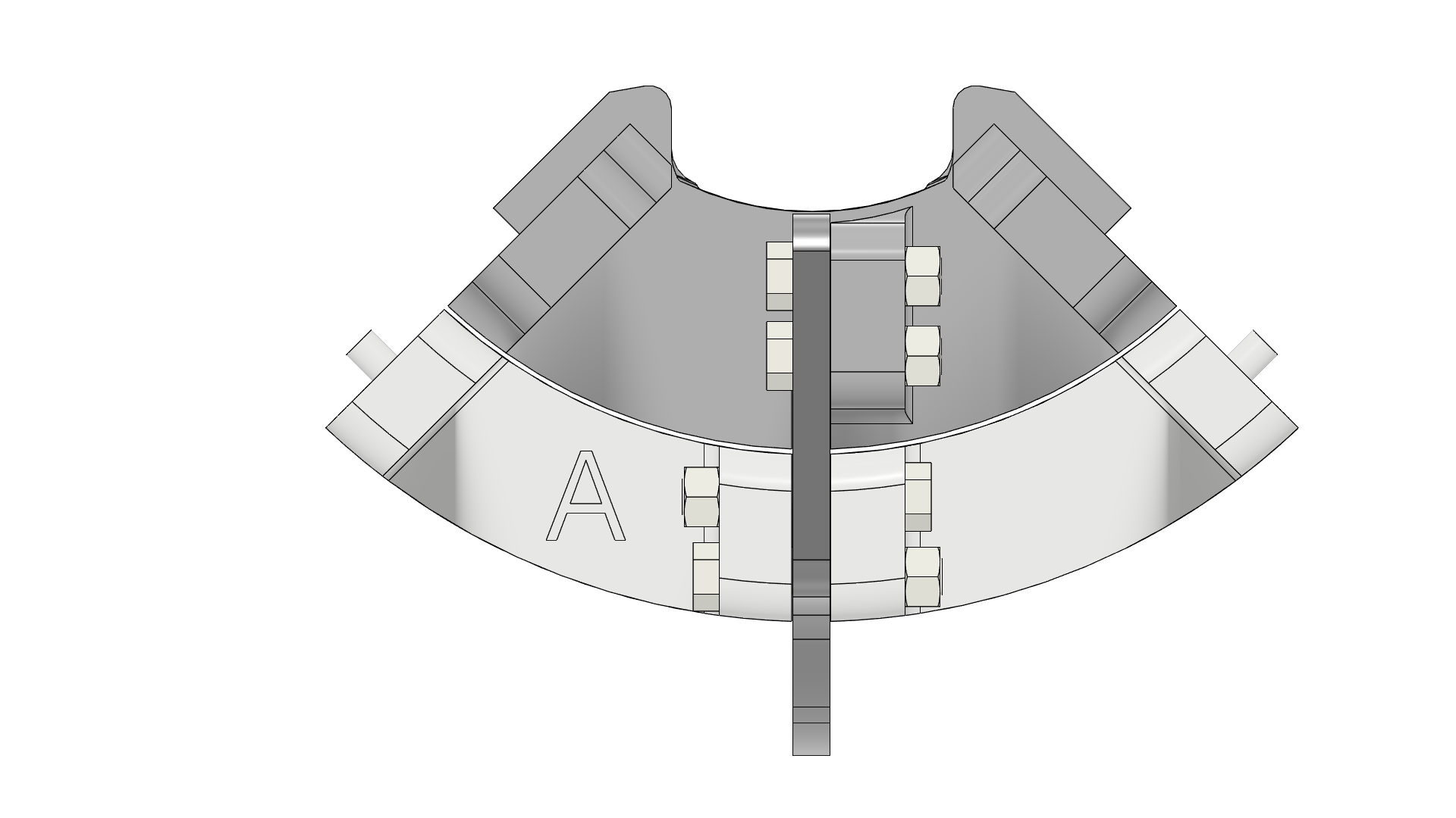 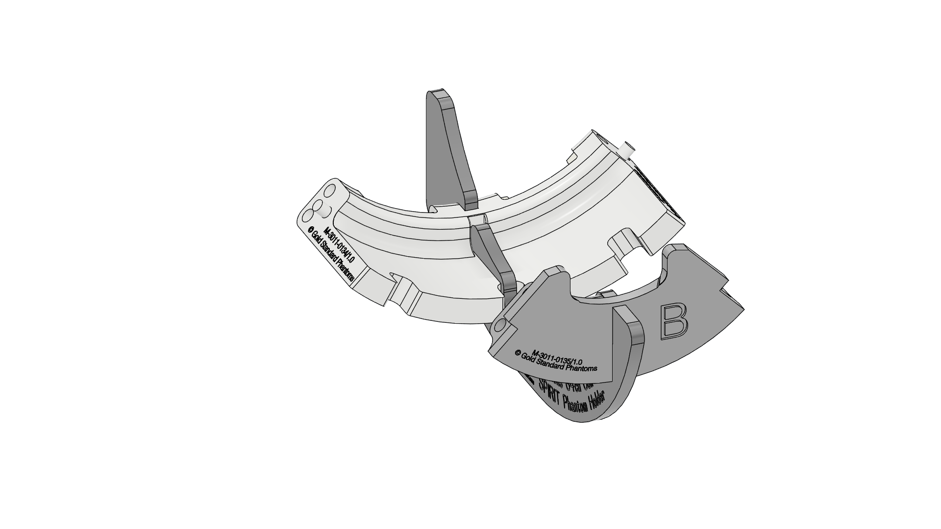 |
| 5 | Add the left support, Part D. The peg on Part B mates with the hole on Part D. | 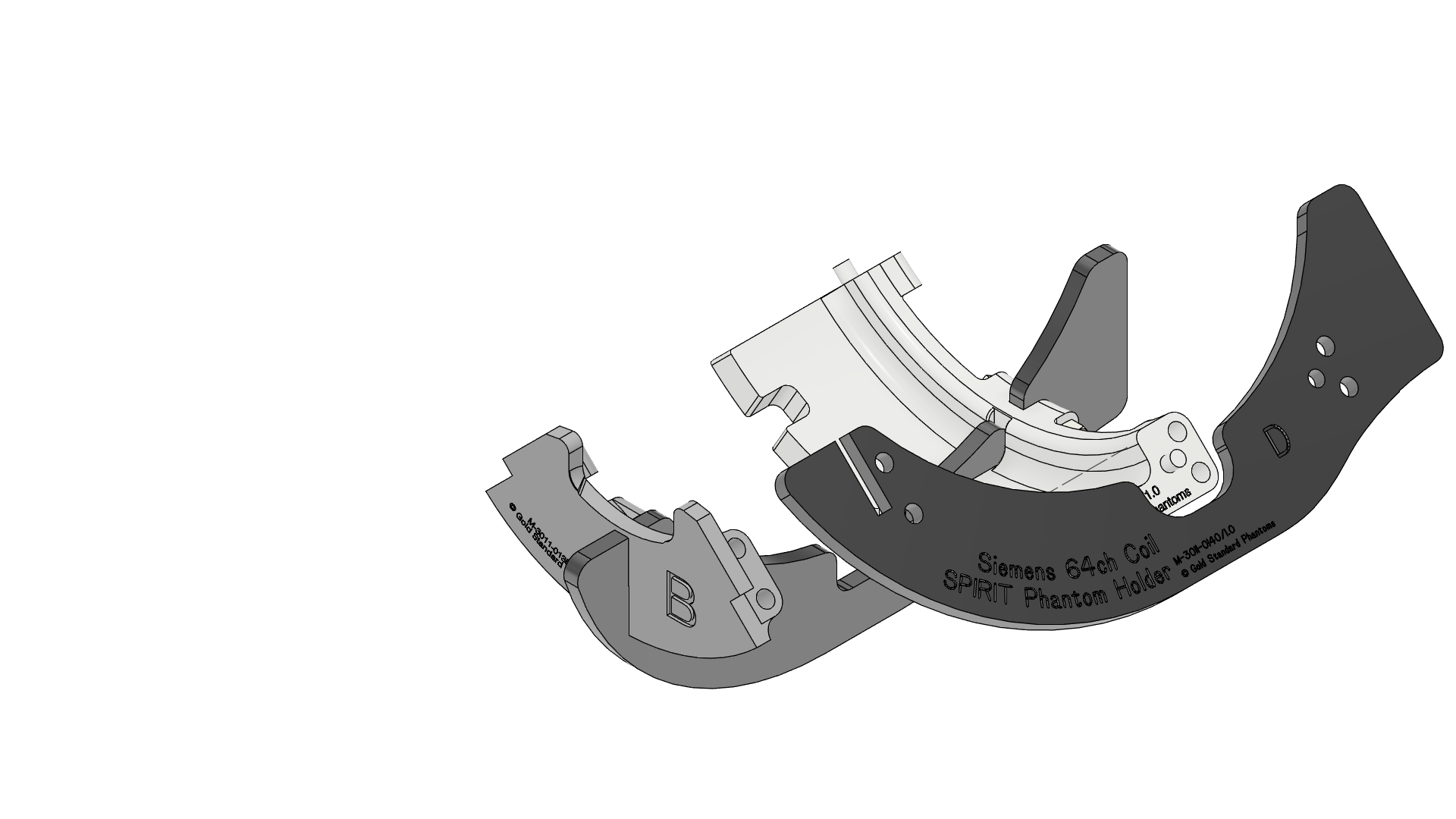 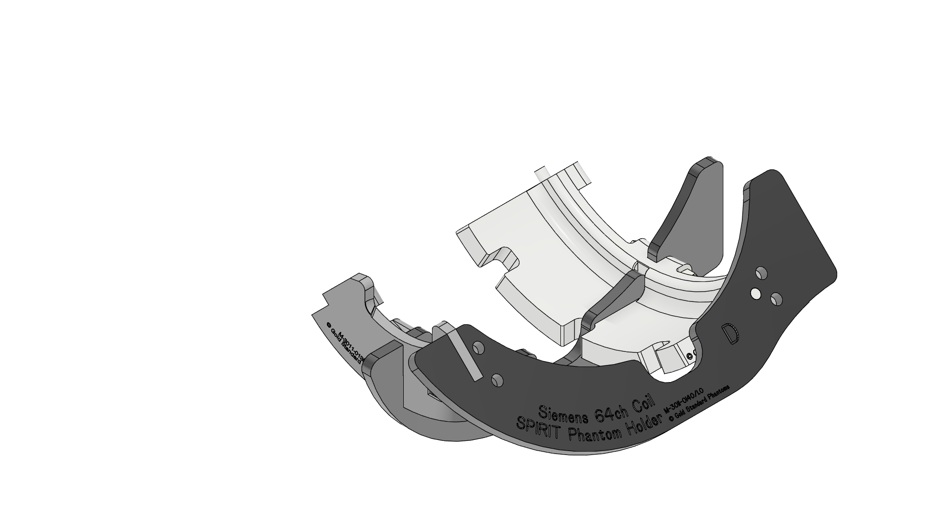 |
| 6 | Fit four F screws into the holes between Part D and parts A and B. Add four H nuts and tighten by hand (finger tight). | 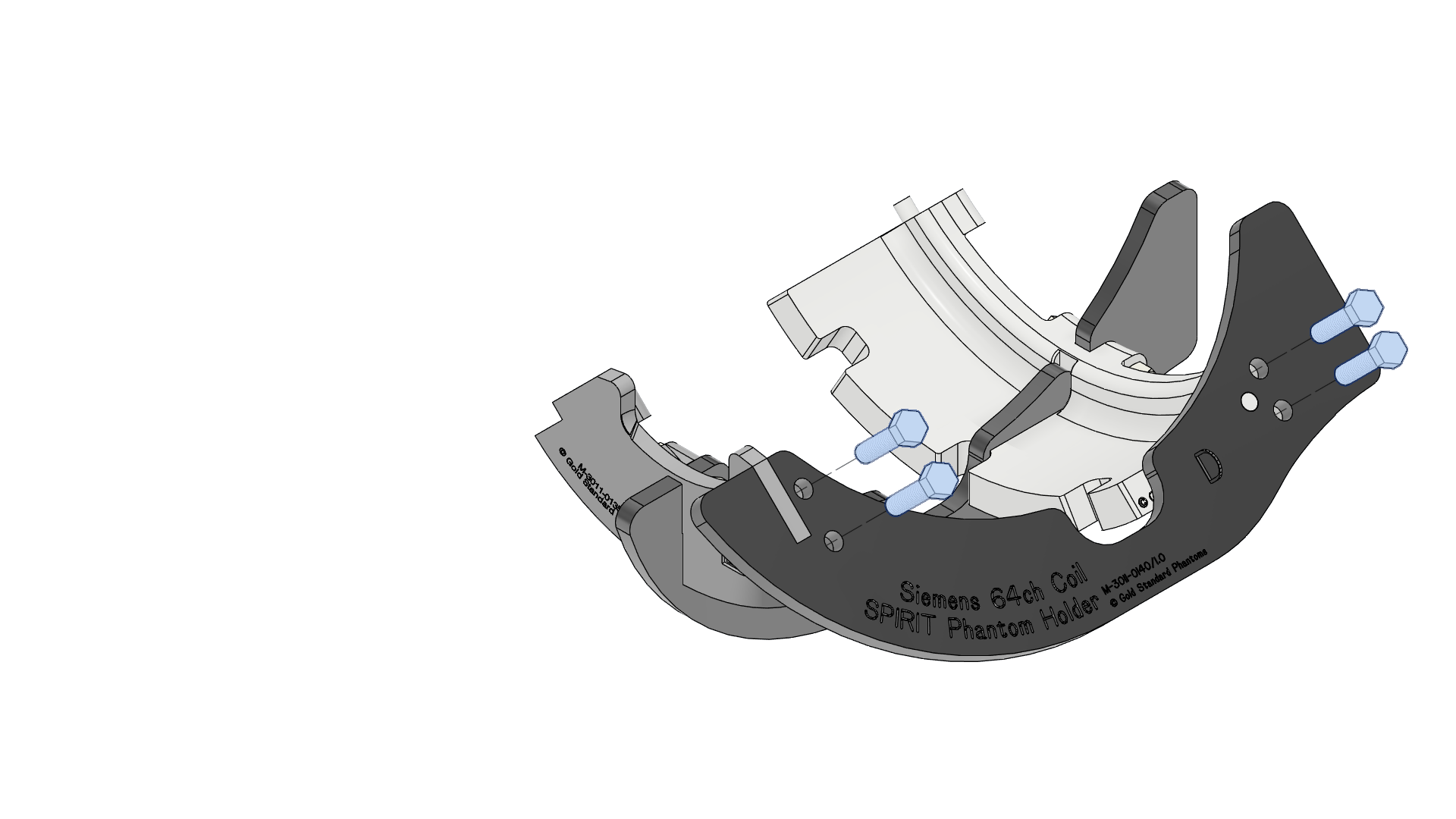 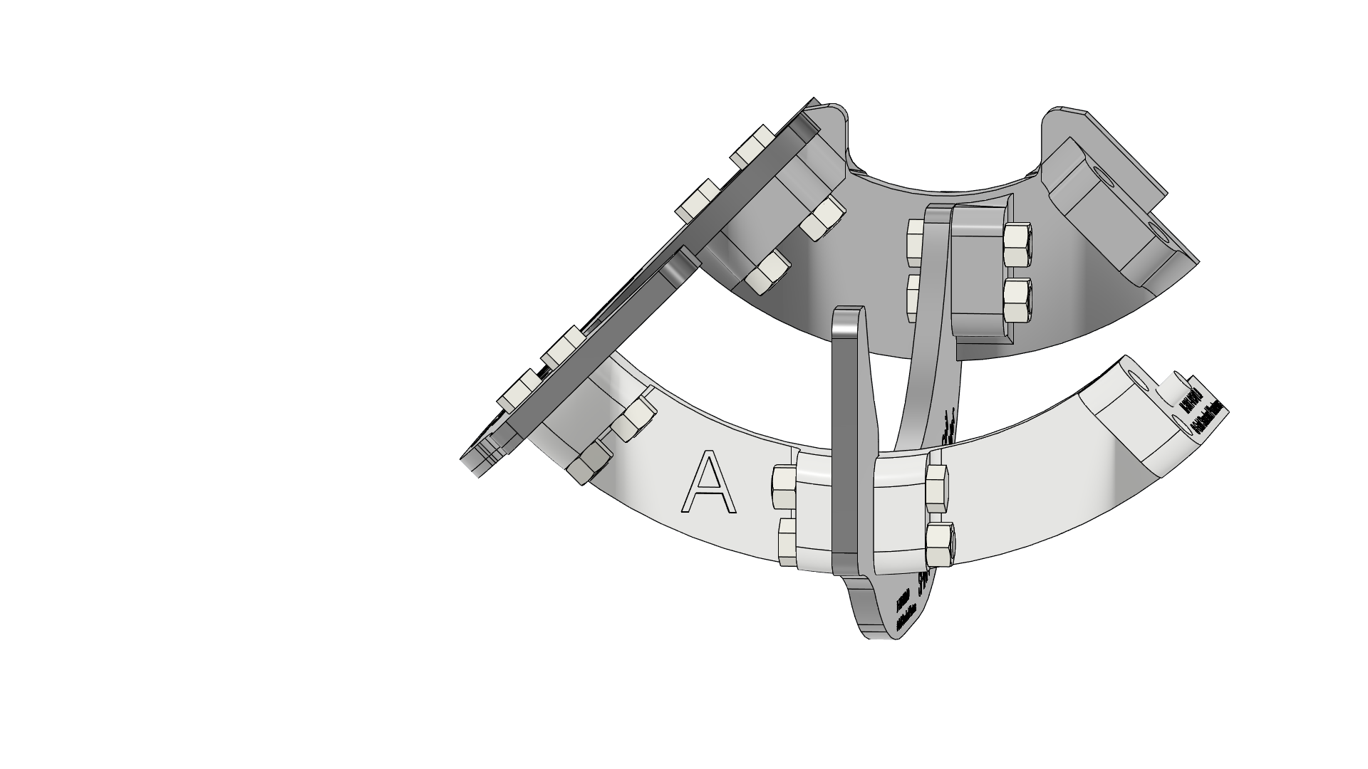 |
| 7 | Add the right support, Part E. The peg on Part B mates with the hole on Part E. | 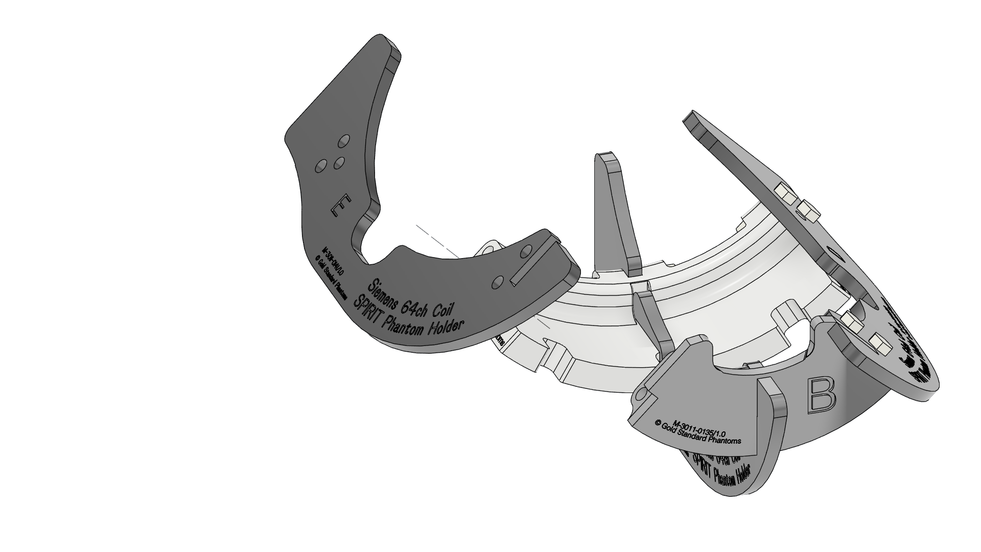 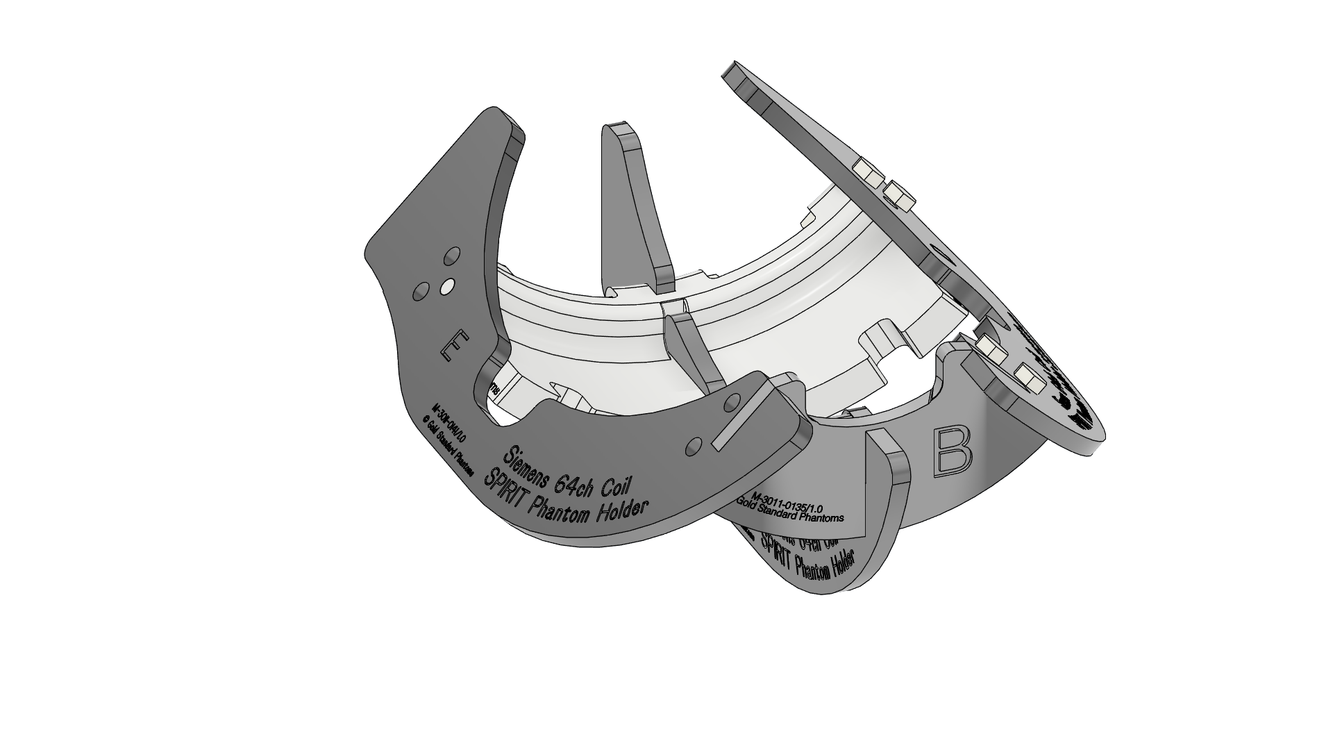 |
| 8 | Fit four F screws into the holes between Part E and parts A and B. Add four H nuts and tighten by hand (finger tight). | 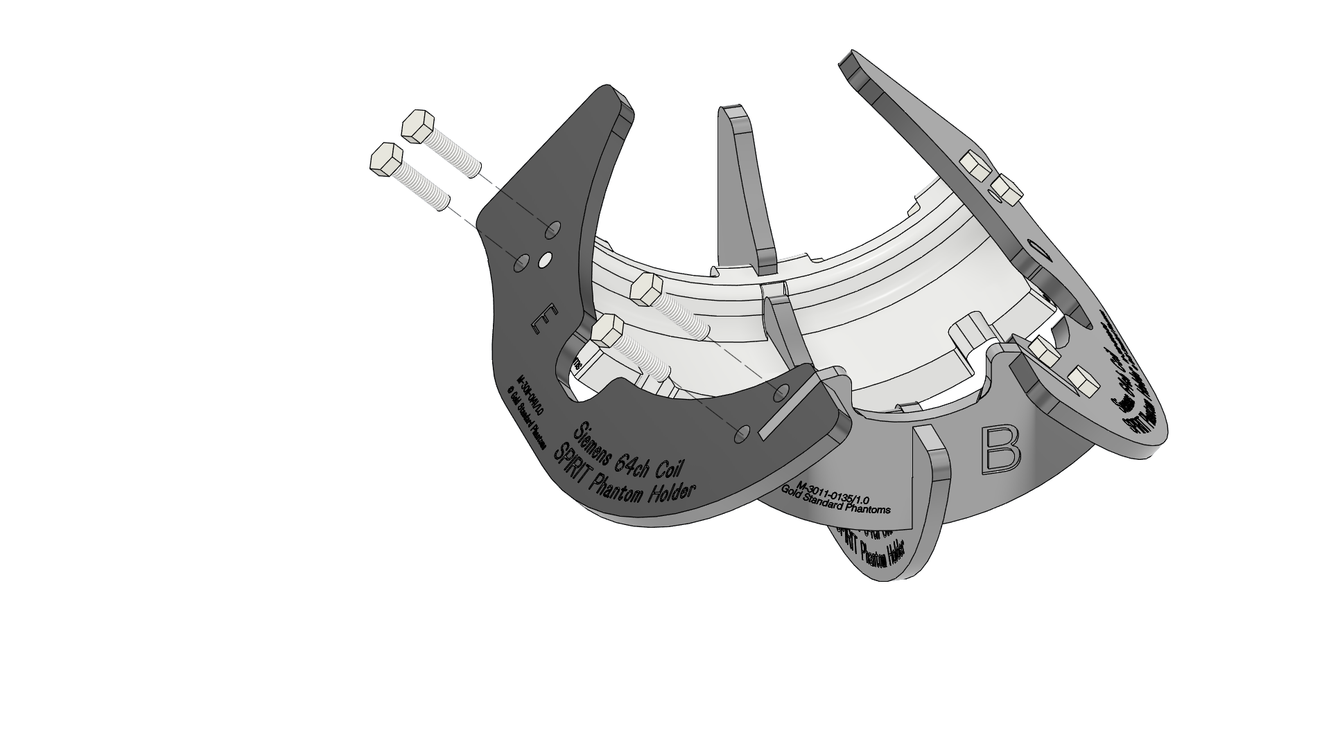 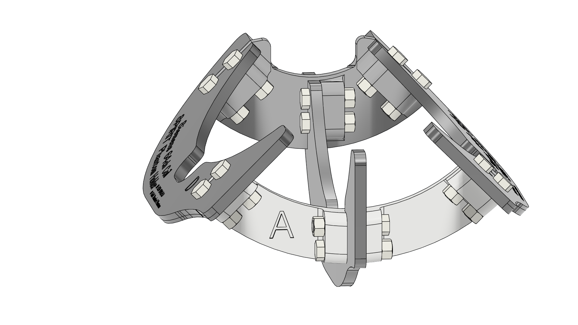 |
| 9 | Congratulations you have completed the assembly of the Phantom holder | 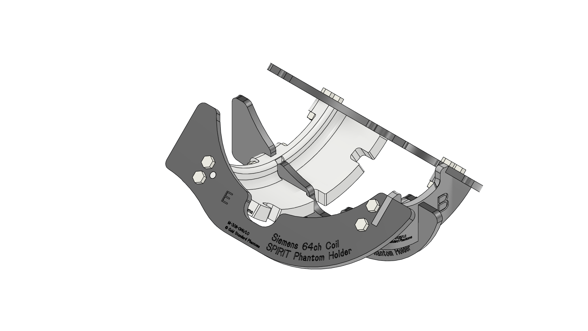 |
Using the Phantom Holder
| 1 | Placing the SPIRIT Phantom The Spirit Phantom holder has notches in Part A that the screws in the phantom fit snugly into, indexing its orientation. The Phantom should be installed in the Phantom Holder with the Label facing up
| 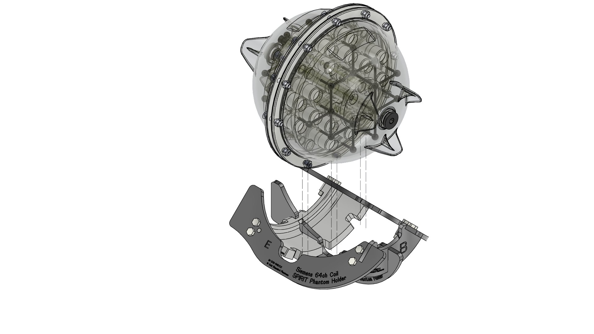 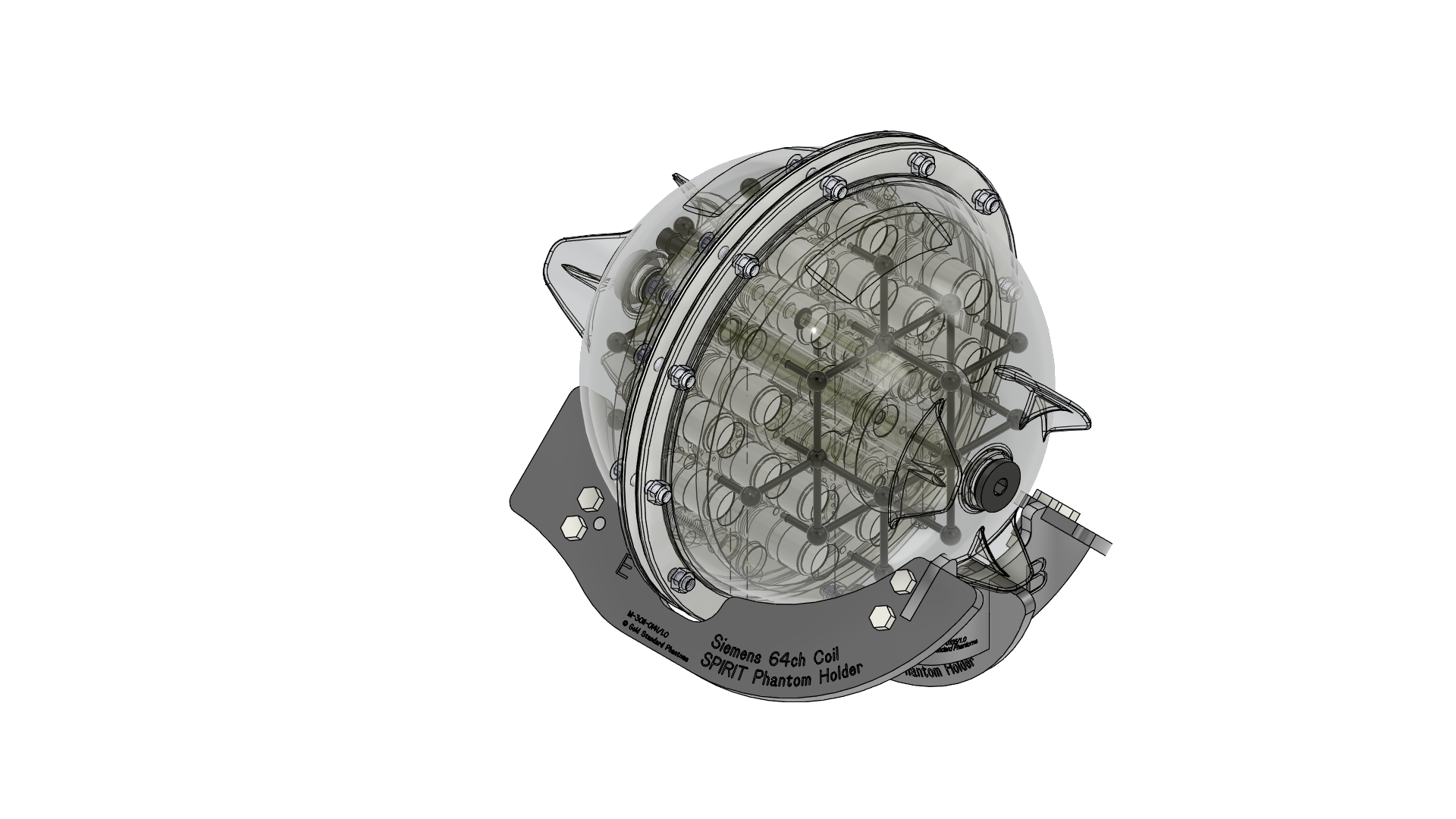 |
| 2 | Placing the holder in the Siemens 64ch Coil The Phantom and phantom holder can now be placed into the Seimens 62 ch head and neck coil | 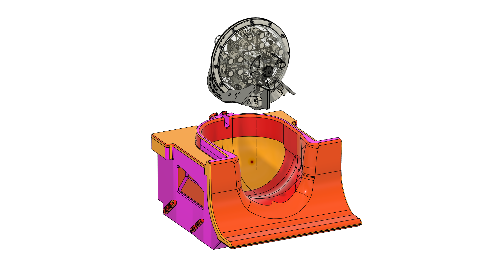 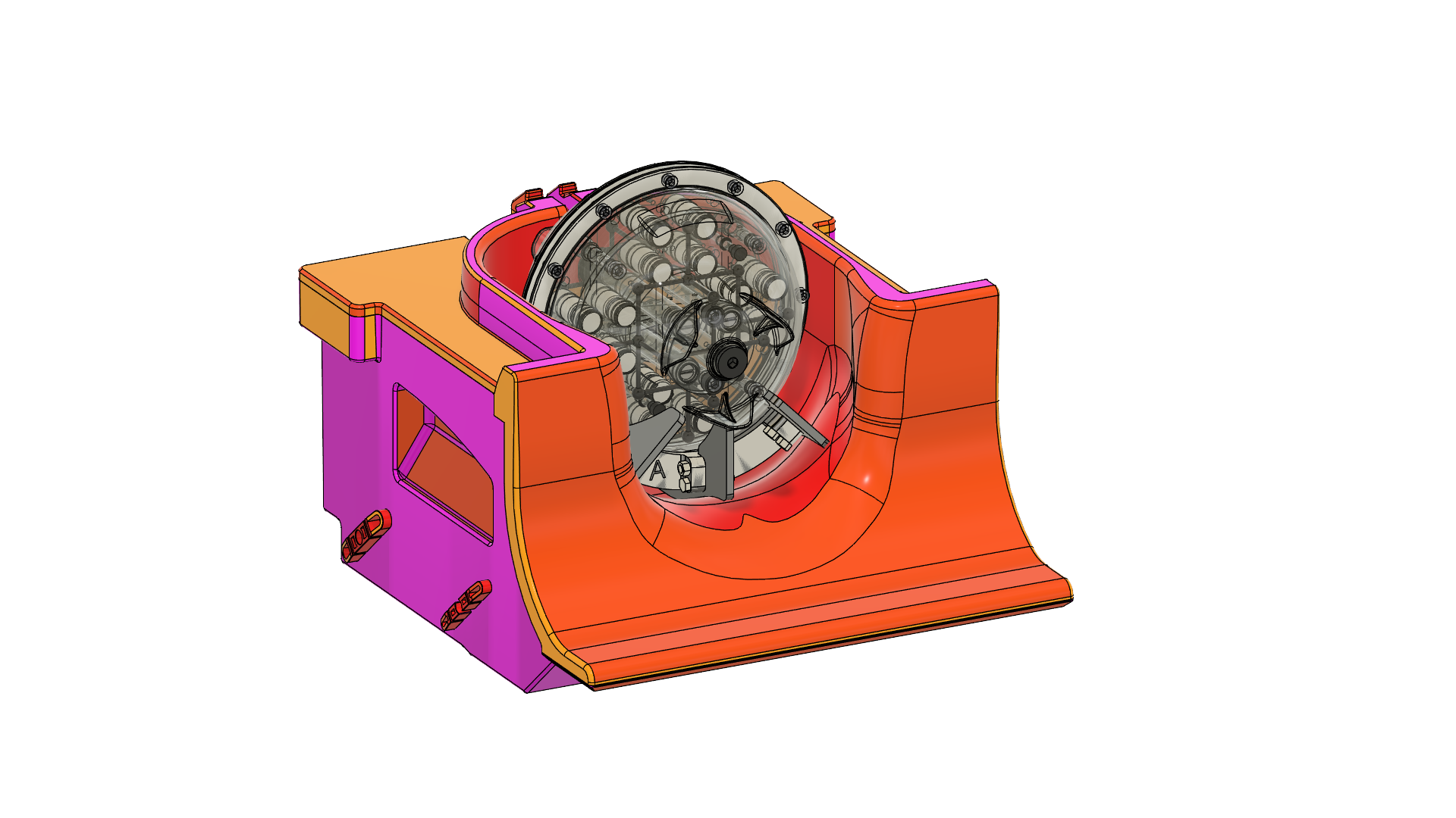 |
| 3 | To ensure the rotational position of the phantom take the rotational alignement jig and place it over the lip of the Coil using the Notch labelled B. The flat part of the jig will sit against the nut on the phantom at the 10 o’clock position. The jig then may be removed. | 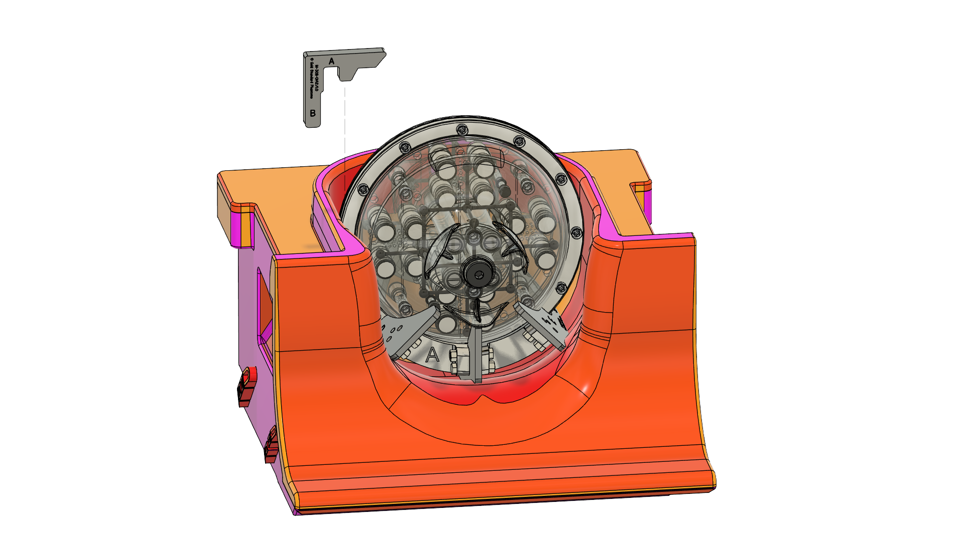 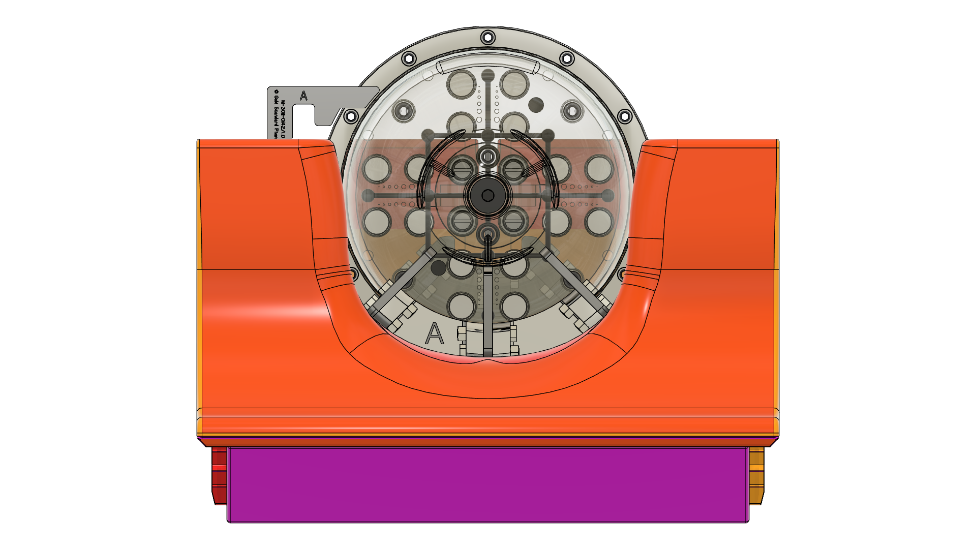 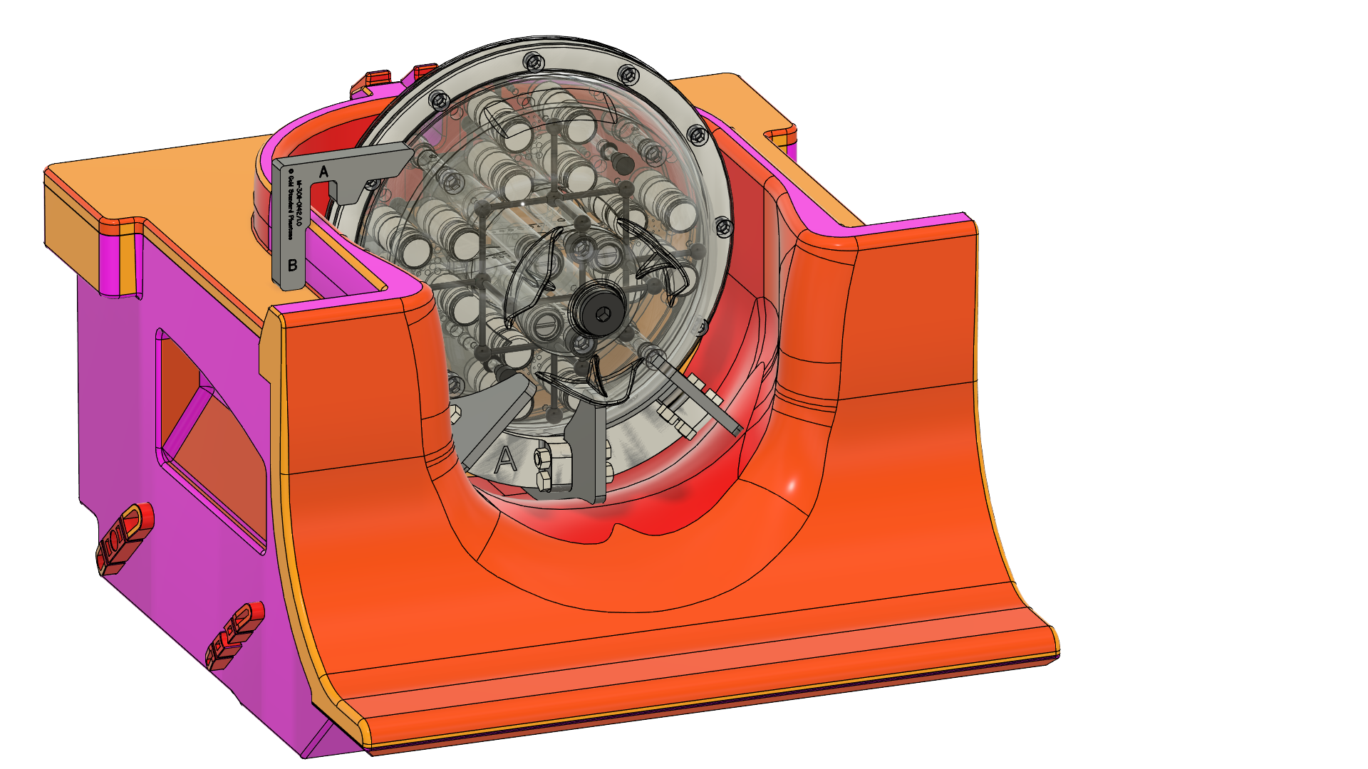 |